
Inspect and Repair the Imported Model
Manual Repair of Imported Models
Parameterize the Imported Model
CST STUDIO SUITE offers powerful import options for geometrical data in both two and three dimensions.
This chapter will provide an introduction on how import options should be used without focusing on the actual dialog boxes. Refer to the online documentation for more information.
The structural import process usually consists of two steps:
Import of the geometrical data and its conversion into ACIS models. Note that the origin of the imported CAD model will automatically be adjusted to the origin of the currently active coordinate system.
Healing of the newly created ACIS models in order to obtain valid geometry.
The first step can be seen as a pure geometric language translation step. All inaccuracies in the imported models remain during this stage. The second step then repairs the data so that valid ACIS models are obtained.
In general, problems during the import and healing process arise from different accuracy levels of the CAD system and the ACIS kernel used in CST STUDIO SUITE. The accuracy of a CAD system is usually the distance for which the system considers two points to be identical. The ACIS kernel uses an accuracy of 1e-6 whereas some other CAD systems operate at accuracies of 1e-3 only.
Assuming that the CAD data have been created on a system with an accuracy level of
1e-3, it may easily contain gaps of this size (which the CAD system would still consider to be closed). Importing such a model into the ACIS kernel afterward would keep these gaps. However, in contrast to the less accurate CAD system, ACIS would not consider these gaps to be closed which may consequently cause failures in creating solids. To circumvent these problems, sophisticated automatic healing technology can be used to close the gaps in the imported model.
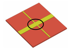
The following picture illustrates this step in the case of a 3D part:

The healing modifies the imported model so that it forms a valid solid shape. The following section discusses the import process in 2D and 3D in more detail.
A variety of files can be imported using Drag and Drop.
CST STUDIO SUITE™ currently supports the following 2D data file formats:
DXF
(Modeling:
Import/Export![]() Import
Import![]() 2D/EDA Files
2D/EDA Files![]() DXF).
This file format contains 2D descriptions of the structure’s surfaces.
It is the preferable format for 2D data transfer from systems that do
not support the SAT file format.
DXF).
This file format contains 2D descriptions of the structure’s surfaces.
It is the preferable format for 2D data transfer from systems that do
not support the SAT file format.
GDSII (Modeling:
Import/Export![]() Import
Import![]() 2D/EDA Files
2D/EDA Files![]() GDSII).
This file format contains 2D descriptions of the structure’s surfaces.
It is the preferable format for 2D data transfer from systems that do
not support the SAT or DXF file format.
GDSII).
This file format contains 2D descriptions of the structure’s surfaces.
It is the preferable format for 2D data transfer from systems that do
not support the SAT or DXF file format.
Gerber files
GERBER
(Single Layer) (Modeling:
Import/Export![]() Import
Import![]() 2D/EDA Files
2D/EDA Files![]() GERBER
GERBER![]() GERBER (Single Layer).
This file format contains 2D descriptions of the structure’s surfaces.
Use this import format for 2D data transfer from PCB CAD systems that
support the RS-274D or RS-274X GERBER file format.
GERBER (Single Layer).
This file format contains 2D descriptions of the structure’s surfaces.
Use this import format for 2D data transfer from PCB CAD systems that
support the RS-274D or RS-274X GERBER file format.
GERBER (Multiple Layers) (Modeling:
Import/Export![]() Import
Import![]() 2D/EDA Files
2D/EDA Files![]() GERBER
GERBER![]() GERBER (Multiple Layers).
This feature allows to import a complete stackup which consists of multiple
gerber layers including the vias. The vias can be defined by drill files
or by gerber files. All gerber files need to have
the RS-274X GERBER format.
GERBER (Multiple Layers).
This feature allows to import a complete stackup which consists of multiple
gerber layers including the vias. The vias can be defined by drill files
or by gerber files. All gerber files need to have
the RS-274X GERBER format.
Simplification Settings (Modeling:
Import/Export![]() Import
Import![]() 2D/EDA Files
2D/EDA Files![]() GERBER
GERBER![]() Simplification Settings).
Use the simplification
settings dialog to reduce the complexity of the model.
Simplification Settings).
Use the simplification
settings dialog to reduce the complexity of the model.
We recommend using the DXF file format whenever possible because this is the most flexible and robust choice for 2D data transfer.
By default (if the option "Import as curves only" is NOT used), the imported 2D elements (lines, arcs, polygons, etc.) will be connected automatically so that they form closed profiles. Additionally a healing option is available which tries to close small gaps in the resulting profiles.
Once a closed profile is obtained, it will automatically
be covered and extruded by the height specified for the corresponding
DXF layer. If no height has been specified, CST STUDIO SUITE will import
the DXF data as an infinitely thin double-sided face. You can use this
face as a basis for further construction. You may, for instance, use the
Modeling:
Tools![]() Shape Tools
Shape Tools![]() Shell Solid or Thicken Sheet
Shell Solid or Thicken Sheet ![]() operation to create a solid from the face.
operation to create a solid from the face.
The following picture shows a typical yet simple model imported from a DXF file:
If you zoom into the structure, you can check the finite thickness of the imported metallization layer:

Please note: Due to the PBA technique, these thin layers do not slow down the solution process for solvers based on hexahedral grids.
Even though the import of 2D files is usually much less critical than the import of 3D models, problems may sometimes occur. The following hints should help to make the import as robust as possible:
Organize your structure into layers. Always put the structural drawing and additional data (such as hatchings, measure lines, text, etc.) on different layers, and only import the structural layers.
Only import those parts you are actually interested in. Since CST STUDIO SUITE needs to build 3D objects from the 2D input data, the complexity of the model is heavily increased during the import process. The deletion of unwanted objects after importing the complete structure is unnecessarily inefficient.
Try to use polygons in the drawing of the 2D files as opposed to a collection of independent lines. Due to some accuracy constraints or a less accurate drawing, independent lines may have gaps, which must be closed with much effort during the import process.
Following these rules will usually yield successful import results. However, if you experience problems, read the Inspect and Repair the Imported Model section later in this chapter to get information on how defects in the model can be resolved.
CST STUDIO SUITE offers import filters for various 3D geometrical CAD formats:
ACIS SAT (Modeling:
Import/Export![]() Import
Import![]() 3D Files
3D Files![]() SAT/SAB). All versions up to ACIS R23
are supported. This is, in general, the most reliable method of importing
structure elements and is thus preferred.
SAT/SAB). All versions up to ACIS R23
are supported. This is, in general, the most reliable method of importing
structure elements and is thus preferred.
STEP
(Modeling:
Import/Export![]() Import
Import![]() 3D Files
3D Files![]() STEP
(203, 214)). This
is an international standard file format for exchanging
data between different CAD/CAM systems. Choose this file format if no
native format like SAT, Pro/Engineer or CATIA is available. Supported version
are 203 and 214 (geometry only).
STEP
(203, 214)). This
is an international standard file format for exchanging
data between different CAD/CAM systems. Choose this file format if no
native format like SAT, Pro/Engineer or CATIA is available. Supported version
are 203 and 214 (geometry only).
Pro/E
Release (Modeling:
Import/Export![]() Import
Import![]() 3D Files
3D Files![]() PRO/E
(Release 16 - Creo 2.0)).
Import
data from PTC’s Pro/Engineer
CAD system.
PRO/E
(Release 16 - Creo 2.0)).
Import
data from PTC’s Pro/Engineer
CAD system.
CATIA
V4 (Modeling:
Import/Export![]() Import
Import![]() 3D Files
3D Files![]() CATIA
Release 4 (4.1.9 - 4.2.4)).
Import
data from Dassault Systemes’ CATIA
Release 4
CAD system.
CATIA
Release 4 (4.1.9 - 4.2.4)).
Import
data from Dassault Systemes’ CATIA
Release 4
CAD system.
CATIA
V5 (Modeling:
Import/Export![]() Import
Import![]() 3D Files
3D Files![]() CATIA
Release 5 (R6 - R22)).
Import
data from Dassault Systemes’ CATIA
Release 5
CAD system.
CATIA
Release 5 (R6 - R22)).
Import
data from Dassault Systemes’ CATIA
Release 5
CAD system.
Autodesk
Inventor (Modeling:
Import/Export![]() Import
Import![]() 3D Files
3D Files![]() Autodesk
Inventor (V6 - V2012)).
Import
data from Autodesk's
Inventor CAD
system.
Autodesk
Inventor (V6 - V2012)).
Import
data from Autodesk's
Inventor CAD
system.
Agilent
ADS files (Modeling:
Import/Export![]() Import
Import![]() 3D Files
3D Files![]() ADS
Model). Import Agilent ADS data up to version 2011.05
. The geometric complexity of the ADS model can be reduced by using ADS
Simplification.
ADS
Model). Import Agilent ADS data up to version 2011.05
. The geometric complexity of the ADS model can be reduced by using ADS
Simplification.
CoventorWare
(Modeling:
Import/Export![]() Import
Import![]() 3D Files
3D Files![]() CoventorWare).
Import CoventorWare SAT files
including the correct material information.
CoventorWare).
Import CoventorWare SAT files
including the correct material information.
Sonnet (Modeling:
Import/Export![]() Import
Import![]() 3D Files
3D Files![]() Sonnet
Model). Import Sonnet project files.
Sonnet
Model). Import Sonnet project files.
IGES
(Modeling:
Import/Export![]() Import
Import![]() 3D Files
3D Files![]() IGES). Versions up to 5.3. This file
format contains accurate descriptions of structure surfaces. After importing
the models it may be necessary to manually repair problems that will be
highlighted after the import has completed. Please refer to the Inspect and Repair the Imported
Model section.
IGES). Versions up to 5.3. This file
format contains accurate descriptions of structure surfaces. After importing
the models it may be necessary to manually repair problems that will be
highlighted after the import has completed. Please refer to the Inspect and Repair the Imported
Model section.
VDAFS
(Modeling:
Import/Export![]() Import
Import![]() 3D Files
3D Files![]() VDA-FS). Versions 1.0 - 2.0 are supported.
The file format contains accurate descriptions of structure surfaces.
As with the IGES import, healing of the model is usually required.
VDA-FS). Versions 1.0 - 2.0 are supported.
The file format contains accurate descriptions of structure surfaces.
As with the IGES import, healing of the model is usually required.
STL
ASCII (Stereolitography) (Modeling:
Import/Export![]() Import
Import![]() 3D Files
3D Files![]() STL). This file format contains only
triangulated approximations of the structure surfaces. The boolean manipulations
of these objects may become very time consuming. In general, this file
format should only be used for very simple structures or when no other
format is available.
STL). This file format contains only
triangulated approximations of the structure surfaces. The boolean manipulations
of these objects may become very time consuming. In general, this file
format should only be used for very simple structures or when no other
format is available.
Object
File (Modeling:
Import/Export![]() Import
Import![]() 3D Files
3D Files![]() OBJ). This file format contains only
triangulated approximations of the structure surfaces. The boolean manipulations
of these objects may become very time consuming. In general, this file
format should only be used for very simple structures or when no other
format is available.
OBJ). This file format contains only
triangulated approximations of the structure surfaces. The boolean manipulations
of these objects may become very time consuming. In general, this file
format should only be used for very simple structures or when no other
format is available.
Voxel
Data (Human Model) (Modeling:
Import/Export![]() Import
Import![]() 3D Files
3D Files![]() Voxel Data). Import biological data in voxel format.
Voxel Data). Import biological data in voxel format.
Mecadtron
(Modeling:
Import/Export![]() Import
Import![]() 3D Files
3D Files![]() Mecadtron). Import Mecadtron
SAT files including the correct material information.
Mecadtron). Import Mecadtron
SAT files including the correct material information.
Microstripes
(Modeling:
Import/Export![]() Import
Import![]() 3D Files
3D Files![]() Microstripes). Import Microstripes
SAT files including the correct material-, units- and frequency information.
Microstripes). Import Microstripes
SAT files including the correct material-, units- and frequency information.
NASTRAN
(Modeling:
Import/Export![]() Import
Import![]() 3D Files
3D Files![]() NASTRAN). Import
NASTRAN files. To reduce the complexity of the model use the dialog
Triangle
Decimation.
NASTRAN). Import
NASTRAN files. To reduce the complexity of the model use the dialog
Triangle
Decimation.
HFSS
(Modeling:
Import/Export![]() Import
Import![]() 3D Files
3D Files![]() HFSS). Import of HFSS
projects including the material information.
HFSS). Import of HFSS
projects including the material information.
Import
Sub-Project (Modeling:
Import/Export![]() Import
Import![]() Sub-Project). Imports an external CST
project. The geometrical data and materials of this project will be imported.
Sub-Project). Imports an external CST
project. The geometrical data and materials of this project will be imported.
The SAT file format is the native data format of the ACIS kernel and should therefore be used whenever possible.
The STL data format contains only facet information. Importing these kinds of data usually becomes problematic when more than one shape of this type is imported and the shapes touch each other. The following picture illustrates this problem:
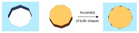
Since the two-faceted representations of the cylindrical hole and the cylinder are not identical, the assembly contains holes and overlapping rather than a cylinder that perfectly fits into the hole.
Please note: The STL import is often most useful in combination with the staircase meshing option. Refer to the online documentation for more information.
The IGES, STEP and VDA-FS data formats are based on standardized file format specifications, in contrast to proprietary file formats such as Pro/E, Autodesk Inventor, CATIA V4 and CATIA V5.
The data translation process consists of two stages. First the CAD system converts and exports its data into a certain file format. Afterwards CST STUDIO SUITE reads the file and converts it into its own internal data structures. It is usually preferable to import the native data format of the CAD system in order to avoid the first data translation step. Since every translation step may entail a loss of accuracy, it is advantageous to avoid unnecessary translation steps.
With regard to standardized CAD data formats, the STEP format is preferable to the IGES or VDA-FS formats because it also contains topology information about the relationship of neighbored faces. This important information must be recreated from pure geometry data if IGES or VDA-FS files are imported.
Therefore, the guidelines as to which data format should be used for which CAD system are as follows:
CATIA V4: Use the CATIA V4 file format.
CATIA V5: Use the CATIA V5 file format.
Pro/E: Use the Pro/E file format.
Autodesk Inventor: Use the Autodesk Inventor or SAT file formats.
ACIS based systems: Use the SAT file format.
Other CAD systems: Try to use the STEP (203, 214) format, if available. Otherwise use the IGES and VDA-FS formats in this order. If these are not available either, use the STL format (which will most likely require staircase meshing).
The following list of rules applies to all types of file formats and should help you get the best results for importing CAD data:
Keep the complexity reasonably low: Bear in mind that you are going to run an electromagnetic analysis with your models. Importing an entire car including details, such as the door locks for instance, will exceed today’s computational resources. Please import only the most relevant parts for highly complex models (e.g. the car’s body).
Avoid unnecessary blends in the CAD model: Excessive application of blends will also increase the complexity in the data. You should always try to avoid unnecessary blends and other complex shape details (e.g. embossed text) in the exported files whenever possible.
Avoid tiny model sizes: Due to the limited numerical precision in the file formats, you should use units in which the model has reasonably large absolute dimensions. If your model has a bounding box diagonal of 0.1 m, for instance, you should export it in mm in order to get a larger absolute diagonal of 100 (mm).
Avoid Boolean operations before exporting the model: Whenever possible, you should try to avoid Boolean operations between parts before exporting the model to a file. In the example of the STL import shown earlier, the problem is due to the insertion of a cylinder into a plate, which then contains a hole. If the insertion were omitted in this case, inserting the imported and healed shapes within CST STUDIO SUITE would not cause any problems. This issue is most critical when faceted CAD data are used (e.g. STL) but still should be considered for the other more accurate data formats as well.
Try different export options: Whenever you experience problems in any of the data translation steps, you should try to use different export options for your CAD system. You may need to experiment a bit in order to find the combination which works best for your system and your type of models.
In general, the option 'Copy file to project' should be activated for the import.
When 'Copy file to project' is activated, the original import file will be copied to the Model/3D sub folder of the project. For the import, the copied file will be converted to a sat file, and will be saved to the Model/3D sub folder of the project, too. During a rebuild, the sat file is usually read except when the copied import file in the Model/3D sub folder is newer.
When 'Copy file to project' is not activated, only the converted sat file will be saved to the project. During a rebuild, the sat file is usually read except when a newer file of the import exists.
This option is available for the following imports: SAT, STL, IGES, VDAFS, STEP, Autodesk Inventor, PROE (Part), CATIA4, CATIA5 (Catpart), Nastran, Microstripes, Conventor, Mecadtron, HFSS, DXF, GDSII, Gerber.
Please note: For CATIA5 Catproduct files and ProE Assembly files this option is always deactivated, and these imports behave like explained above.
As outlined above, an automated healing step is necessary after importing a model from foreign CAD data. Therefore you should always use the option Healing in the CAD data import dialog boxes.
After importing and healing the data, a message box will appear informing you of the status of the model. The following picture shows such a message box as it appears for a STEP file import:

Some shapes have been imported and healed without any problems (100% OK). However, some other shapes show minor defects indicated by a percentage of 98-99%. Clicking on the shape default:import_3 and selecting Healing Details would, in this example, provide a text output window. In order to understand the healing process better, it is advantageous to know the meaning of this output. Thus we will provide some explanations of the most important information in this text step by step.
The first section gives some statistics about the solid after the import and before the actual healing process starts:
SIMPLIFICATION ANALYSIS :
=========================
INPUT STATISTICS :
296 Splines,
0 Planes,
0 Spheres,
0 Cylinders,
0 Cones,
0 Tori
0 Straights,
0 Circles,
0 Ellipses,
757 Intcurves,
Simplification tolerance set to 0.0001
Planes-Only option set OFF
In the case investigated here, the imported shape consists of spline faces only. However, the healing technology tries to reduce the complexity of the imported data by converting as much of the imported spline faces to analytical trimmed surfaces as possible (simplification). The result of this stage is shown in the next section:
SIMPLIFICATION CALCULATION RESULTS :
====================================
CALCULATED AT TOLERANCE = 0.0001 :
Expected spline conversions
116 Planes,
2 Spheres,
114 Cylinders,
8 Cones,
48 Tori
SIMPLIFICATION FIX RESULTS :
============================
Simplification tolerance = 0.0001
no. of initial splines = 296
no. of final splines = 8
Number of analytics made from splines:
116 Planes,
2 Spheres,
114 Cylinders,
8 Cones,
48 Tori
757 Intcurves,
115 Intcurves,
408 Straights,
234 Circles,
0 Ellipses,
The simplification step is able to simplify 288 of the originally 296 spline faces to analytic geometry (e.g. planes, spheres, cylinders, etc.). The next section in the text files gives information on the original status of the model’s geometry:
GEOMBUILD ANALYSIS :
====================
geom build tol = 10
analytic solver tol = 0.0101
no. of edges = 757
no. of bad edges = 177
no. of coedges = 1514
no. of bad coedges = 360
no. of vertices = 471
no. of bad vertices = 51
no. of bad tangent edges = 44
no. of bad tangent edges analytic = 37
no. of G1 bad tangent edges analytic = 39
no. of bad tangent edges uv_uv = 1
no. of bad tangent edges boundary uv_uv = 1
no. of bad tangent edges uv_nonuv = 6
no. of bad tangent edges nonuv_nonuv = 0
no. of bad tangent edges 3_4_sided = 7
no. of surfaces = 296
no. of discontinuous surfaces = 0
percentage of good geom = 92
A lot of elements (171 edges and 51 vertices) have somehow invalid geometry data indicating that this model clearly needs healing. The next sections in the text file give more involved information which is not addressed in this introduction. However, the final section in the text file shows the result of the healing process:
GEOMBUILD FIX RESULTS :
=======================
Statistics of the healed body after geombuild fix :
no. of edges = 757
no. of bad edges = 2
no. of coedges = 1514
no. of bad coedges = 29
no. of vertices = 471
no. of bad vertices = 2
no. of bad tangent edges = 0
no. of bad tangent edges analytic = 0
no. of G1 bad tangent edges analytic = 7
no. of bad tangent edges uv_uv = 0
no. of bad tangent edges boundary uv_uv = 0
no. of bad tangent edges uv_nonuv = 0
no. of bad tangent edges nonuv_nonuv = 0
no. of bad tangent edges 3_4_sided = 0
no. of surfaces = 296
no. of discontinuous surfaces = 0
percentage of good geom = 99
Automatic healing is quite successful in this case. Only two edges and two vertices are still invalid.
After getting the general information that there
are still some defects in the model, it is important to localize the problems.
Usually the automatic healing will convert the incorrect elements to tolerant
objects. By applying tolerances, the modeler is able to perform a limited
set of structural modifications on the model even if it is not 100% valid.
Thus all erroneous elements become tolerant elements in the final stage
of automatic healing. These tolerant elements can easily be visualized
by selecting Modeling:
Tools![]() Shape Tools
Shape Tools![]() Healing Tools
Healing Tools![]() Model Analysis
Model Analysis![]() Show Tolerant Edges, respectively.
Show Tolerant Edges, respectively.
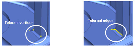
In this example, the problems arise mainly due to the imported blends’ faces. Whenever you encounter such problems in the healing process, we recommend contacting your CAD drawing department first. On many occasions a careful inspection of the CAD model at these locations may show some minor defects or inaccuracies in the original model. After revising the drawing and re-importing the structure, you should check whether the problem disappeared. If improving the quality of the CAD data is not possible, or if the problem still persists, you may need to manually repair the model.
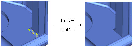
In the example shown here, it is sufficient to delete
the inaccurate blend using the Face Modifications tool. If you plan to
re-apply the blend later and do not know its radius, you should measure
it before its removal. Afterward you only need to select the blend’s face
using the face pick tools and use Modeling:
Tools![]() Modify Locally
Modify Locally![]() Modify Face
to remove the face.
Modify Face
to remove the face.
The blend can then be re-applied by selecting the
edge and using Modeling:Tools![]() Blend
Blend![]() Blend Edges.
Blend Edges.
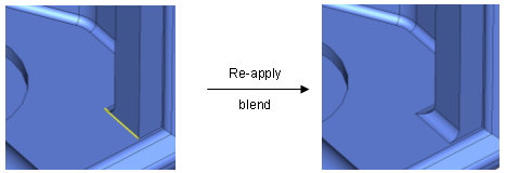
The procedure above is typical for the manual healing of invalid blends. However, in many cases it is advantageous to avoid these blends before exporting the model from the original CAD system. Quite often, the blends have little or no effect on the electromagnetic behavior of the structure, so there may be no need to re-apply them.
Remember the best rule for CAD data exchange: Keep it simple!
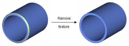
In the second example, the following steps explain how unnecessary details can be simply removed from the model. Let us assume that the pin shown in the picture below does not affect the electromagnetic properties and should thus be removed from the model:
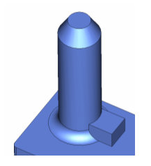
The easiest way to achieve this is to use the Remove
Feature tool after selecting all faces of the unwanted structure detail.
To easily obtain this face selection, activate Modeling:
Picks![]() Picks
Picks![]() Pick Edge Chain (Shift+E) and double-click
on the edge that connects the detail with the rest of the model:
Pick Edge Chain (Shift+E) and double-click
on the edge that connects the detail with the rest of the model:
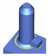
After properly selecting this edge, activate Modeling: Picks![]() Picks
Picks![]() Pick Face Chain (Shift+F) and double-click
on one of the detail’s faces:
Pick Face Chain (Shift+F) and double-click
on one of the detail’s faces:
Now all faces connected to the currently picked
one will be selected. However, the face selection will stop at previously
picked edges. By properly selecting the picked edges, you can advise the
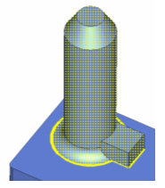
tool to select the faces of the unnecessary structure detail only. Finally
the Face
Modifications dialog in Modeling:
Tools![]() Modify Locally
Modify Locally![]() Modify Face
can be used to remove the shape and automatically close the gaps:
Modify Face
can be used to remove the shape and automatically close the gaps:
After importing the CAD models, a warning message will be shown if the automatic healing procedure could not fix all problems.
There exist a variety of different problems that may not all be explained here. Please contact the technical support for assistance.
Apply Modeling:
Tools![]() Shape Tools
Shape Tools![]() Healing Tools
Healing Tools![]() Model Analysis
Model Analysis![]() Check Shape (
Check Shape (![]() ) presenting a window frame to see if the
shape contains any errors. Use Modeling:
Tools
) presenting a window frame to see if the
shape contains any errors. Use Modeling:
Tools![]() Shape Tools
Shape Tools![]() Healing Tools
Healing Tools![]() Model Analysis
Model Analysis![]() Check Level to
vary the accuracy of the check between quick,
normal and intensive. To receive more
detailed information of the current state of its faces, edges and/or vertices,
use the following properties:
Check Level to
vary the accuracy of the check between quick,
normal and intensive. To receive more
detailed information of the current state of its faces, edges and/or vertices,
use the following properties:
|
|
Modeling:
Tools |
|
|
Modeling:
Tools |
|
|
Modeling:
Tools |
|
|
Modeling:
Tools |
The affected elements will be highlighted. Dangling edges belong only to one face, junction edges belong to more than two faces, spline elements result from various spline evaluation processes, bad elements have no proper association to the selected shape, and tolerant elements possess a certain tolerance range regarding their dimensions due to repair procedures concerning the overall shape structure.
If tolerant elements occur, the maximum tolerance
of the associated shape is given by Modeling:
Tools![]() Shape Tools
Shape Tools![]() Healing Tools
Healing Tools![]() Model Analysis
Model Analysis![]() Show
Maximum Tolerance.
Show
Maximum Tolerance.
Furthermore, Modeling: Tools![]() Shape Tools
Shape Tools![]() Healing Tools
Healing Tools![]() Model Analysis
Model Analysis![]() Show
Bounding Box Problems (
Show
Bounding Box Problems (![]() ) points out any bounding-box problems of
the shape.
) points out any bounding-box problems of
the shape.
Iit is possible to remove faces using Modeling:
Tools![]() Shape Tools
Shape Tools![]() Healing Tools
Healing Tools![]() Model Healing
Model Healing![]() Delete
Zero Faces
or Delete
Faces for Selected Edges.
Delete
Zero Faces
or Delete
Faces for Selected Edges.
Another solution in many cases is to cut away
the problem parts using boolean operations. Afterwards, you should invoke
the automatic healing operation again by selecting the particular shape
and then choosing Modeling: Tools![]() Shape Tools
Shape Tools![]() Heal
Shape (
Heal
Shape (![]() ). If this healing still fails, you may convert the shape to
its faceted
representation (Modeling:
Tools
). If this healing still fails, you may convert the shape to
its faceted
representation (Modeling:
Tools![]() Shape Tools
Shape Tools![]() Healing Tools
Healing Tools![]() Model Healing
Model Healing![]() Faceted
Shape Representation
(
Faceted
Shape Representation
(![]() )).
)).
Finally, we recommend that you repeat the steps above until the automatic healing operation no longer shows any errors.
If you frequently deal with CAD import from less accurate CAD systems, we recommend you to attend a training class to obtain more up-to-date information about repairing models from your particular CAD system.
Heal faces
Imported shapes
from DXF, GDSII files may have self-intersecting faces. Select only the
shape with the self-intersecting face and use Modeling:
Tools![]() Shape Tools
Shape Tools![]() Healing Tools
Healing Tools![]() Model Healing
Model Healing![]() Heal
Self Intersecting Shape (
Heal
Self Intersecting Shape (![]() ) to repair this shape.
) to repair this shape.
Circumventing problems with imported models
In some cases, boolean operations with imported models will fail with an error message such as ”inconsistent face/face intersections.” This will usually happen when the boolean operation attempts to intersect almost coplanar faces that contain a tiny offset between them (this offset typically arises either from inaccurate CAD models).
A simple way to circumvent this problem is to
offset the faces or adjusting the radius by using Face
Modifications dialog and the Face
Constraints dialog in Modeling:
Tools![]() Modify Locally to circumvent this accuracy
problem.
Modify Locally to circumvent this accuracy
problem.
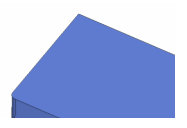
Consider the following situation: We have imported a brick and a cylinder where the cylinder just fits into a hole in the brick.
However, due to some inaccuracy problems, the cylinder does not fit exactly into the brick, thereby causing an overlapping shapes error during the mesh generation. The typical method for solving the problem of again inserting the cylinder into the brick will fail with an inconsistent face/face intersections error.
In this case,
you may simply make the hole a bit smaller by picking the cylindrical
face of the hole and using the Set Radius
feature of the Face
Constraints (Modeling:
Tools![]() Modify Locally
Modify Locally![]() Define Face Constraints) mode.
Define Face Constraints) mode.
Afterwards, the
insert operation will still fail because of the small offset between the
planar faces of the cylinder and the brick. This problem may be circumvented
by offsetting either the cylinder’s face or the brick’s face by a small
amount (e.g. 1e-4) using the Face
Modifications dialog in Modeling:
Tools![]() Modify Locally
Modify Locally![]() Modify Face (either in Move
face or in Offset face
mode).
Modify Face (either in Move
face or in Offset face
mode).
The insert operation will now work properly. In general, users who work with imported models require training to become efficient. The quality of the automatic CAD repair operations will be improved continuously, but there will always be a few cases where manual interaction will become necessary.
This section only provides some ideas on how imported models can be healed manually if the automatic healing is unable to fix all problems. However, there are many more options available. Optimal strategies may also differ according to your structure and the originating CAD system. We strongly recommend that you attend a specialized training class on this topic in order to obtain best results. Please contact your support center for more details.
Quite often, the aim of the electromagnetic analysis is not just to know the given structure’s behavior but also to optimize it according to various goals. Such optimizations require the ability to modify the model even if it was obtained by importing a CAD data file.
CST STUDIO SUITE offers the outstanding possibility of parameterizing shapes for which no construction history exists by using Local Modifications. The Getting Started manuals contain a section explaining how these tools are generally applied. You should familiarize yourself with this functionality before you proceed to the next sections since they focus on the application of these operations to imported solids.
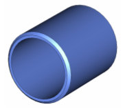
For the following explanations, let's assume you wish to change the radius of the cylinder’s outer face shown in the picture below:
You could simply start the Face Constraints mode
(Modeling:
Tools![]() Modify Locally
Modify Locally![]() Define Face Constraints), select the
corresponding face and apply the set the radius
to yield the following result:
Define Face Constraints), select the
corresponding face and apply the set the radius
to yield the following result:
In order to close the resulting gaps, the chamfer’s face automatically extends up to its intersection with the modified cylindrical face. This results in an enlargement of the chamfer which is probably not what is required.
This problem can be circumvented by removing the chamfer, changing the face’s radius, and finally re-applying the chamfer. If you don’t know the size of the chamfer, you will need to measure it first by picking two points and checking the distance:
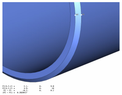
In this example, you will find the chamfer has a
width of 0.2. Now you can pick the chamfer’s face and remove it with the
Face Modifications
mode in Modeling:
Tools![]() Modify Locally
Modify Locally![]() Modify Face:
Modify Face:
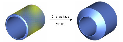
The next step is to change the radius of the face and to re-apply the chamfer as shown in the picture below:
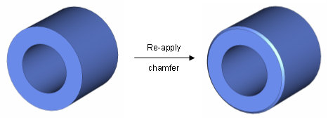
You can use a variable to specify the new radius of the face (by entering it in the edit field or by pressing the Parametrize... button in the dialog). This will allow you to fully parameterize (and thus later optimize) the model even though it has been imported from CAD data.
The example outlined above should provide you with some idea as to how imported models can be parameterized by using local modifications. Since many different (more or less efficient) solutions exist to achieve such a parameterization, we recommend that you visit a specialized training class on this topic. Please contact your support center for more information.
Export
ACIS SAT files (Modeling:
Import/Export![]() Export
Export![]() 3D Files
3D Files![]() SAT). Export the native file format
for all ACIS based modelers. This is in general the most reliable format
to exchange data between such systems. The export covers all ACIS versions
from R1.6 - R23.
SAT). Export the native file format
for all ACIS based modelers. This is in general the most reliable format
to exchange data between such systems. The export covers all ACIS versions
from R1.6 - R23.
Export
IGES files (Modeling:
Import/Export![]() Export
Export![]() 3D Files
3D Files![]() IGES). This file format contains accurate
descriptions of the structure’s surfaces. It is the preferable format
for data transfer to systems that do not support the SAT file format.
IGES). This file format contains accurate
descriptions of the structure’s surfaces. It is the preferable format
for data transfer to systems that do not support the SAT file format.
Export
STEP files (Modeling:
Import/Export![]() Export
Export![]() 3D Files
3D Files![]() STEP).
Export the international standard STEP file format.
STEP).
Export the international standard STEP file format.
Export
STL files (Modeling:
Import/Export![]() Export
Export![]() 3D Files
3D Files![]() STL). This file format contains only
triangulated approximations of structure surfaces. This file format should
be used only when triangulated data is necessary or when no SAT or IGES
files are supported by the receiving system.
STL). This file format contains only
triangulated approximations of structure surfaces. This file format should
be used only when triangulated data is necessary or when no SAT or IGES
files are supported by the receiving system.
Export
NASTRAN files (Modeling:
Import/Export![]() Export
Export![]() 3D Files
3D Files![]() NASTRAN). This file format contains
only triangulated approximations of structure surfaces. This file format
should be used only when triangulated data is necessary or when no SAT
or IGES files are supported by the receiving system.
NASTRAN). This file format contains
only triangulated approximations of structure surfaces. This file format
should be used only when triangulated data is necessary or when no SAT
or IGES files are supported by the receiving system.
Export
DXF files (Modeling:
Import/Export![]() Export
Export![]() 2D Files
2D Files![]() DXF). Export 2D cross sections of the
structure and the active xy- or the uv-plane as a DXF file. Multiple layers
parallel to the plane can be requested for export by picking points in
the according heights.
DXF). Export 2D cross sections of the
structure and the active xy- or the uv-plane as a DXF file. Multiple layers
parallel to the plane can be requested for export by picking points in
the according heights.
Export
GDSII files (Modeling:
Import/Export![]() Export
Export![]() 2D Files
2D Files![]() GDSII). Export 2D cross sections of
the structure and the active xy- or the uv-plane as a GDSII file. Multiple
layers parallel to the plane can be requested for export by picking points
in the according heights.
GDSII). Export 2D cross sections of
the structure and the active xy- or the uv-plane as a GDSII file. Multiple
layers parallel to the plane can be requested for export by picking points
in the according heights.
Export
Gerber files (Modeling:
Import/Export![]() Export
Export![]() 2D Files
2D Files![]() Gerber). Export 2D cross sections of
the structure and the active xy- or the uv-plane as a Gerber file in the
format RS-274X.
Gerber). Export 2D cross sections of
the structure and the active xy- or the uv-plane as a Gerber file in the
format RS-274X.
These export options allow the export of graphical data to files or Windows clipboard.
Export main view to clipboard (Home:
Clipboard![]() Copy
Copy![]() Copy View to Clipboard).
Copy View to Clipboard).
Export
main view to BMP files (View:
Export![]() BMP).
BMP).
Export
structure to POV (Persistence of Vision ray-tracer) file (Modeling:
Import/Export![]() Export
Export![]() 3D Files
3D Files![]() POV).
POV).
These export options allow the export of results data for usage in external post-processing.
Exporting Results Overview, Export BMP File, Export POV File, Drag and Drop,Import Problem Handling