|
微波射频仿真设计 |
|
|
微波射频仿真设计 |
|
| 首页 >> Ansoft Designer >> Ansoft Designer在线帮助文档 |
|
Design Verification > OverlapTo CommandsThis section describes the following OverlapTo commands: • OverlapToErrors • OverlapToPolygons • OverlapToEdges
Input: One or two DV layers (containing polygons) Constraint (operator and distance) Measurement region qualifier (optional) Orientation Qualifiers (optional) Intersecting Edge qualifier (optional) Raw/Merged qualifier (optional)
Output: DV layer – Type varies with the command. OverlapToErrors outputs a DV layer containing error clusters. OverlapToPolygons outputs a DV layer containing polygons. OverlapToEdges outputs a DV layer containing edges.
Description: Overlap is the distance between inside edges, of intersecting geometry, that face each other. The single layer version checks the overlap between different geometries on the same layer. The two layer version checks the overlap between geometry on one layer and geometry on the other layer. This is an edge to edge check, not corner to corner, or corner to edge.
This is a symmetric operation. The order of the input layers does not change the results.
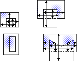
Two edges are considered overlapping if the two geometries intersect but neither contains the other and the edges are inside facing. Arrows in the following diagrams indicate edges that are overlapping.
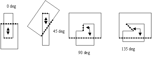
Edges are considered to face each other for overlap checking only if the angle between the inside of one edge and the outside of the other is less than 180 degrees. Collinear edges are not considered facing. The following diagram illustrates angles between inside edges:
The arrows in the following figures indicate the edge pairs that are checked when considering the facing requirement and using default orientation and intersecting qualifiers: Acute Also, Not Obtuse, Parallel Also, Not Perpendicular, and Not Intersecting:
Single Layer Overlap
Two Layer Overlap The first layer has the dot fill pattern and the second layer is empty. The command looks for the overhang of dot geometry from white geometry.
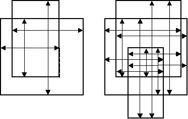
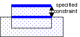
• OverlapToError results are clusters of segments that meet the specified constraint. Each error segment indicates the portion of the geometry edge that meets the constraint. The error clusters are returned in a DV layer. The heavy lines in the illustration that follows show the portions of edges that are returned as one error cluster.
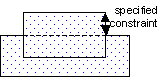
• OverlapToPolygons results are any polygons that have at least one edge that meets the specified constraints. The polygons are returned in a DV layer. Both polygons in the following illustration are returned.
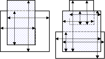
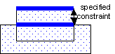
• OverlapToEdges results are segments of edges that meet the specified constraints. These segments retain information about the polygon they were created from. This information allows the edges to be used as input to other DV commands. The segments are returned in a DV layer. The heavy lines in the illustration that follows show the segments that are returned as edges. They are not clustered, and they retain information about the directions inside and outside of the polygon and sibling relationship.
The constraint amount may be given with or without units. If no units are specified the current default length units are used.
Supported operators:
Qualifiers may be specified to constrain the edges checked. The defaults, if qualifiers are not specified, are Round (measurement region), Acute Also, Not Obtuse, Parallel Also, Not Perpendicular, Not Adjacent, and Merged (geometry).
Example (JScript): var layer1 = DVChecker.ImportLayer("trace"); var overhangLayer1 = DVChecker.OverlapToErrors(Array("<", "5mm"), layer1, Array( "Round", "Acute Also", "Not Obtuse", "Parallel Also", "Not Perpendicular")); DVChecker.SaveLayer(overhangLayer1, "overhang errors", "overhang < 5 on trace layer"); var layer2 = DVChecker.ImportLayer("ground"); var overhangLayer2 = DVChecker.OverlapToErrors(Array("<", 5), layer1, layer2, Array( "Round", "Acute Also", "Not Obtuse", "Parallel Also")); DVChecker.SaveLayer(overhangLayer2, "overhang errors", "trace overhanging ground by < 5");
HFSS视频教程 ADS视频教程 CST视频教程 Ansoft Designer 中文教程 |
|
Copyright © 2006 - 2013 微波EDA网, All Rights Reserved 业务联系:mweda@163.com |
|