|
Time Signal View
Here, you may view your simulation’s time signals. The
naming convention for the time signals differs, depending on whether simultaneous port mode excitation
or sequential port mode excitation is activated.
Naming Convention for Time Signals with Sequential
Port Mode Excitation
|

|
|
|
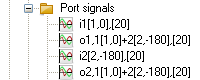
One single mode per port:
|
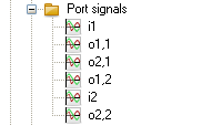
Waveguide port,
discrete
port, or nearfield
source input signals start with i, output signals start with o, and
the numbers describe the port where the signal is recorded and which port
was stimulated.
The labels are also listed on the right-hand side of the ,
each color associated to a displayed curve. |
|
Multiple modes per port:
|
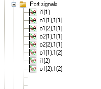
If multiple modes are excited per port, the signal labels are extended
by the mode number in round brackets. The mode numbers are located directly
behind the port number. |
|
Plane wave excitation:
|
The label "Plane wave" indicates
the excitation time signal of a plane wave. |
|
S-Parameter:
|
The behavior of the port signals in frequency domain is presented in
the corresponding subfolders. |
Naming Convention for
Time Signals with Sequential Port Mode Excitation
|
One single mode per port:
|
In addition to the naming convention for sequential
port mode excitation, the labels for the input and output signals are
extended by the excitation amplitude and phase shift / reference frequency
setting with respect to the time delay setting if automatic labeling is
turned on in the Port Mode Excitation Selection dialog. |
|
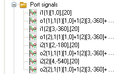
Multiple modes per port:
|
If multiple modes are excited per port, the signal labels are extended
by the mode number in round brackets. The mode numbers are located directly
behind the port number. Every mode of the different ports can be stimulated
independently by a different excitation signal. If the stimulating signal
is not the project's reference signal, the name of this excitation signal
is also included in the port mode control sequence. Because this naming
procedure leads to very long control sequences, it is advisable to use
user-defined labels.
An example is shown below. |
|
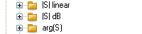
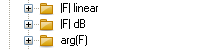
Normalized DFT magnitudes and phases:
|
The behavior of the port signals in frequency domain is presented in
the corresponding subfolders. |
Example
The following two examples point out the naming
convention for time signals with simultaneous port excitation activated.
The upper example uses a phase shift definition with a reference frequency
of 20; the lower example uses an equivalent time delay definition. Port
1 is stimulated with the reference signal, therefore no information about
the excitation signal is displayed. The both modes of port 2 are stimulated
with the excitation signal signal1 that is indicated by displaying the
excitation signal's name in the port mode control sequence.
See also
Post
Processing Views, Navigation
Tree, Waveguide
Port Overview, Discrete
Port Overview, Field Source Overview


HFSS视频教程
ADS视频教程
CST视频教程
Ansoft Designer 中文教程
|
|
