|
微波射频仿真设计 |
|
|
微波射频仿真设计 |
|
| 首页 >> Ansoft Designer >> Ansoft Designer在线帮助文档 |
|
System Simulator > Step 3: Choosing the Maximum Ratio Control VariableOnce the frequency response of a linear electrical RF
sub-design is obtained, the impulse response is extracted from the frequency
response by means of the inverse FFT operation and the pre-defined variable
MAX_RATIO (0 < MAX_RATIO MAX_RATIO is a critical parameter used to determine the actual length of the impulse response used for discrete time simulation. Since the inverse FFT of the frequency response yields an impulse response of length K/2 samples, not all of these samples will be used in the actual discrete time domain simulation. Starting at the last impulse response sample at time Kts/2 and moving towards t = 0 (see Figure 9), the pre-defined variable MAX_RATIO is used to truncate the impulse response at the point where the ratio of the impulse response local maximum to the global maximum is ≥ MAX_RATIO. Thus, specifying a smaller MAX_RATIO value will typically result in longer impulse responses (and longer simulation time) but more accuracy. The default value for MAX_RATIO is 1e-10, which should produce the most accurate results. At the expense of accuracy, the user may specify larger values for MAX_RATIO if a shorter simulation time is desired. A graphical illustration of the effects MAX_RATIO has on determining the length of the impulse response is shown below.
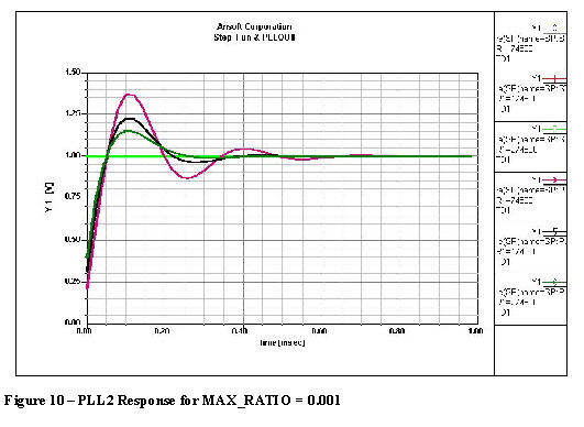
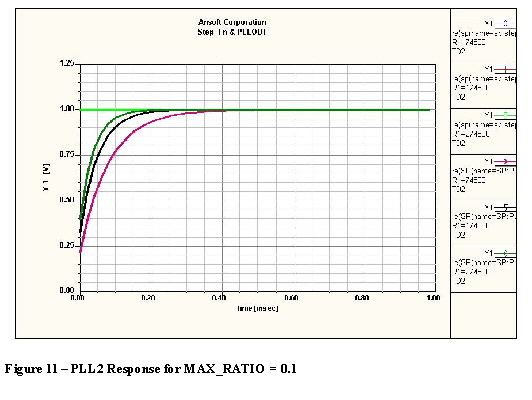
Consider the PLL example discussed above. The responses shown in Figures 10 and 11 below reflect two different values for the MAX_RATIO control parameter, namely 0.001 in Figure 10 and 0.1 in Figure 11, with a fixed sampling rate of 50kHz. Clearly, the impact of choosing a larger MAX_RATIO (Figure 11) can be seen. This is due to the fact that a larger MAX_RATIO resulted in a premature truncation of the impulse response of the PLL electrical loop filter, and consequently, the simulation results are inaccurate. In general, a longer discrete time impulse response (smaller MAX_RATIO) requires a longer simulation time, but will tend to yield more accurate results.
HFSS视频教程 ADS视频教程 CST视频教程 Ansoft Designer 中文教程 |
|
Copyright © 2006 - 2013 微波EDA网, All Rights Reserved 业务联系:mweda@163.com |
|
 1). Refer to the
AM and PLL2 examples.
1). Refer to the
AM and PLL2 examples.