Areas
Edit Layout New
Area
New
Area
The dialog box is also available via Navigation
Tree: AreasNew
Area. A
right mouse click on Areas
opens a drop-down menu where the user is able to call the New
Area dialog box:
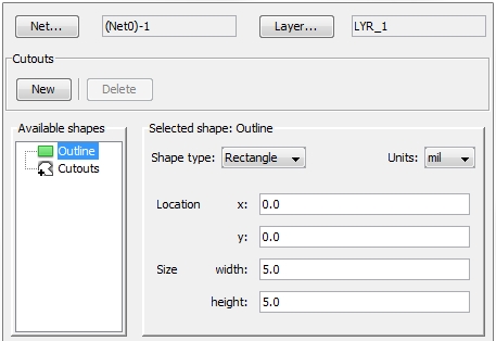
An area consists of one Outline.
In addition to this outline the area can have an arbitrary number of Cutouts. The form of a cutout is defined
exactly as a outline but its area is interpreted as "negative"
in order to punch out the corresponding hole.
Net... / Layer...: A new area
has to be assigned to a certain net on a certain layer. In the figure
above net (Net0)-1 on layer LYR_1 was selected.
Cutouts frame: Inside
the frame a new cutout can be generated by pressing the button New.
A new cutout is automatically added to the list
of Cutouts inside the frame Available shapes.
Available shapes frame: The
frame contains the Outline and
an empty list of Cutouts by default.
By selecting the Outline item
with the left mouse button its default shape definition is displayed in
the Selected shape frame on the
right side.
Units: This field allows the
user to select the unit the geometrical entries below should refer to.
After entering the geometry a change of the units inside this field does
not change the geometric size of the area anymore.
Selected shape frame: There
are four different shape types which can be defined inside this frame
Rectangle defined by:
Location: Defines the lower left point
of the rectangle with the help of a pair of (x, y) coordinates
Size: Defines the width (extension in
x-direction) and the height (extension
in y-direction)
Circle defined by:
Diameter: Defines the circle's diameter
Center: Defines the circle's center
with the help of a pair of (x, y) coordinates
Polygon consists of a list of points which
are to be defined inside the Points
frame. The tool bar on the right provides five functions:
Arc
Outline consists of a list
of arc segments. Every arc segment is defined by a point,
a segment type and the corresponding
radius ( in case of segment type
equals clock-wise or counter
clock wise).
All areas are stored in Navigation
Tree: Areas. Selecting
a certain area and performing a right mouse click
opens a drop-down menu where the user is able to call the Edit
dialog box, which is similar to the New
Area dialog. In order to edit the area one has simply to edit the
corresponding entries inside the dialog box. An example of an existing
area to be edited is shown in the figure below:

Inside the Edit Area dialog
box there is an additional Shaping frame.
It includes two functions allowing for repairing and smoothing critical
area shapes, which might lead to meshing problems:
Repair
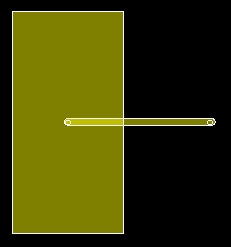
An area overlapping with another structure (trace, area), which does
not belong to the same net, is not allowed and will be reported as an
error from the Layout Check (see
Layout
Check). The Repair function
allows the user to introduce a slot of a certain width along the overlapping
border of the two structures in order to separate the two structures.
The figure below shows an trace intersecting with an area:
Pressing the Repair button
within the Area Edit dialog box
of the area will display the Repair
Shape dialog box as shown in the figure below:
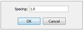
The Spacing value defines the
width of the slot to be introduced. The units of the width are according
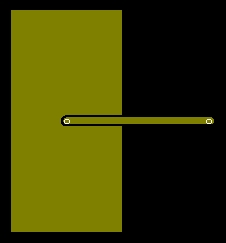
to the specified length unit. After pressing OK
the area is repaired as shown in the figure below.
Smoothing
When existing PCB layouts are imported via the EDA
import it sometimes occurs that some areas have bumpy
shapes. Rugged, bumpy shapes can cause failures during meshing and, as
a consequence, instabilities during the simulation. Smoothing helps to
reduce the number of points of a bumpy polygon and therefore, smoothed
shapes can be meshed more efficiently. The figure below shows the corresponding
dialog box:
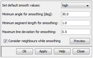
Set default smooth
values: Provides a set of values for the three parameter fields:
Minimum angle for smoothing,
Minimum segment length for smoothing
and Maximum line deviation for smoothing.
There are four different sets of values:
self-defined:
Allows the user to set the parameters on his own
moderate:
Value set for a moderate smoothing
high:
Value set for a high order of smoothing
extreme:
Value set for a very high order of smoothing
Minimum angle for
smoothing: Sets the minimum angle
Minimum segment
length for smoothing: The values are interpreted with the specified
length units.
Maximum line deviation
for smoothing: Specifies the maximal value which the smoothed polygon
is allowed to deviate from the original polygon. The values are interpreted
with the specified length units. Setting this parameter to zero means
to switch off smoothing.
Consider neighbours
while smoothing: This flag prevents the smoothing function from
creating overlaps between shapes next to the smoothed one.
Preview:
Allows the user to preview the smoothed area in the Main
View and allows the user to check the result in advance.
Edit the areas's geometry by mouse: This second way of editing an area can
be done if the Legacy Viewer is
activated (see Layout
Viewer). If a
certain area has been selected and the corresponding Edit
Area dialog box has been opened,
the area itself will be highlighted in the Main
View as shown in the figure below:
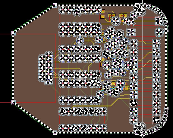
All defined shapes (outline and cutouts) are marked and displayed with
the help of a black-and-white rubber band. Small squares in light blue
color indicate all points that can be picked and moved in order to change
the corresponding shapes. After switching the mouse pointer into the Selection mode with
View: Mouse
ControlSelection
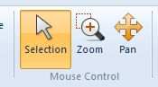
a certain square symbol from any shape (the outline or any cutout)
can be picked and dragged as it was done in the figure below:
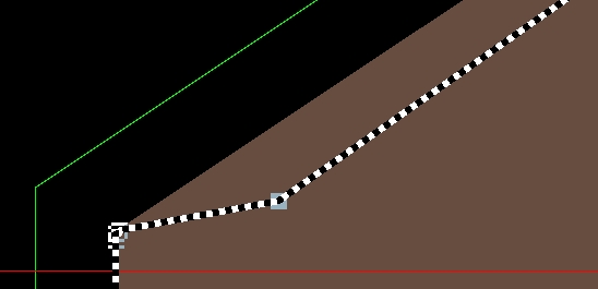
The values of the corresponding point of the corresponding shape (inside
the dialog box) will be changed automatically. In order to acknowledge
the new position of the point, the button Apply
has to be pressed.