ADS2009--���������·�������/ͨ��/��Ƶ/IC��Ƹ�������
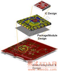
Advanced Design System (ADS2009) is a co-design platform for high-frequency and high-speed ICs, packages, modules and boards. It enables co-design and co-verification of multi-technology components against target system specifications, helping designers to understand component interactions that can affect signal integrity and wireless system performance. Catching these interactions early in the design cycle prevents costly rework during final hardware integration.

Market Pressures Drive Co-Design
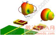
MIMO Antennas
Market pressures in consumer wireless electronics are driving exponential growth in functionalities that must be integrated into same-size and same-price packages. For example, the latest 4G LTE phones must also remain backward compatible with 3G and 2G modes. These smart phones also must have Bluetooth, WiFi and Multiple Input, Multiple Output (MIMO) capabilities, requiring multi-antennas operating over multi-frequency bands. These pressures force high-frequency and high-speed components to be packaged into smaller volumes and closer proximity, often causing undesired interactions. Because costs and delays must be kept low, multiple available technologies are integrated onto the PCB instead of designing it all onto an integrated circuit (IC).
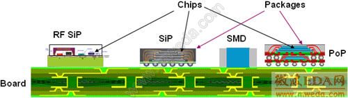
Designing the Physical Layer of Wireless Systems
The RF physical layer of any wireless system requires the successful integration of multi-technology components to meet the wireless system's specs such as LTE, WiMAX™, WiMedia, Wireless HD, etc.

Motivation for Co-Design: Reducing the Risk of Designing in Isolation
A simple model illustrates the motivation for co-design: Imagine your IC, module and board each has 90% chance of success when implemented in hardware (HW).
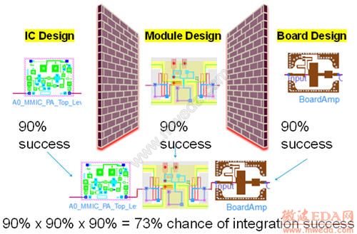
Risk increases when more components are integrated
If you integrate them together when they are already in hardware, the chance of success = 90% x 90% x 90%, or 73%. If you co-design these components together before fabricating hardware, the chance of success for the integrated HW remains at 90% because you have analyzed their unexpected interactions upfront to eliminate integration uncertainty. Co-design reduces risk of failure by 17% in this simple case. When you extrapolate this risk reduction to a complex wireless or high-speed communication system, the return on investment is significant. Without co-design, designers often over-specify components to mitigate risks. Making them more costly and more challenging to design.
Example: Preventing Failed Design Spins
Below is an example of three perfectly working components:
- An RFIC power amplifier designed in Cadence and brought in as a Spectre netlist through ADS 2009 Dynamic Link with Cadence.
- A Dual Flat No-Lead (DFN) package with low loss and good impedance match.
- A Balun implemented on Low Temperature Co-Fired Ceramic (LTCC).
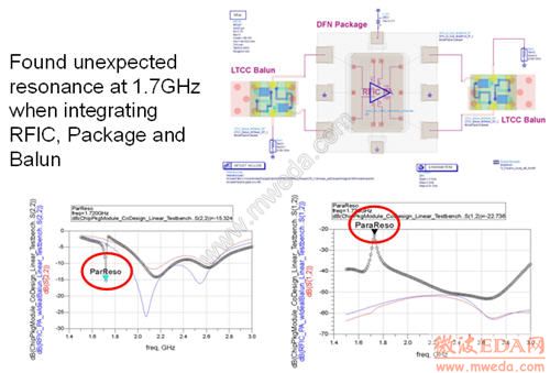
However, when these components were integrated and co-verified in ADS 2009, the RFIC response was altered by an unexpected resonance. Co-design caught the failed design before hardware fabrication and also shows interoperability with the Spectre netlist from Cadence.
ADS2009 Front-End Co-Design Platform
Co-design has three important aspects:
- Methodology of concurrent verification of all components together against the target system specifications as soon as they become available, either in the form of simulated designs or actual off-the-shelf parts.
- Infrastructure that supports the front end co-design methodology by providing a simulation platform that supports co-simulation across multi-technology domains, combining models defined in the time, frequency, numeric or physical domains obtained through either simulation or measurements so that they can be concurrently verified by different designers using common system verification libraries
- Interoperatbiltiy with backend co-design platforms from Mentor or Cadence to complete the physical implementation.
Example ADS 2009 Co-Design Methodolgy: Complete Multi-Technology 4G LTE System Design
Here is an example of implementing the front-end co-design methodology in ADS 2009 with the complete multi-technology design of a 4G LTE wireless handset that comprises RFIC, MMIC, LTCC RF modules, PCB RF amplifier and MIMO antenna with adaptive matching for multi-band and multi-position operations.
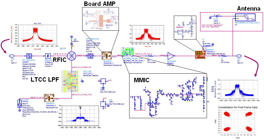
Complete Multi-Technology 4G LTE System Design
�Ŵ�
ADS2009 Co-Design with Instrument-Grade Accuracy for Further Risk Reduction
ADS 2009 employs instrument-grade accuracy in 4G LTE system verification by employing the same LTE analysis algorithms used in Agilent instrumentation. The following image shows the simulated LTE specifications verified with Agilent��s 89600 Vector Signal Analyzer (VSA), which is also used when prototype or final hardware is fabricated.
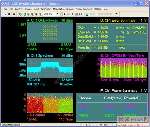
Simulation and measurement share the same analysis algorithm
ADS2009 Co-Design includes MIMO Antenna for Diversity and Adaptive Matching
MIMO Antennas
With multiple antennas needed for multi-band MIMO communications in LTE and WiMAX, the characteristics of multi-antennas within a phone operated in various phone-human proximity positions must be taken into account for the design of adaptive antenna matching network to satisfy the LTE system performance. When integrated with its companion Electromagnetic Professional (EMPro) 3D EM software, ADS 2009 enables this type of co-design methodology to reduce very expensive antenna and mechanical casing rework on the completed phone.
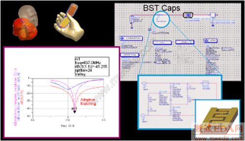
ADS 2009 Co-Design includes MIMO antenna for diversity and adaptive matching
ADS 2009 Infrastructure Supports Front-End Co-Design
The infrastructure in ADS 2009 that supports front-end co-design includes:
- A simulation platform for multi-technology �C faster, higher capacity through multi-threading, acceleration, parallelism, and intelligent algorithms.
- Model support for multi-technology �C accommodate accurate models from measurement of off-the-shelf parts, electromagnetic simulators, behavioral and transistor level descriptions, netlists from HSPICE or Spectre, and signal stimulus data to and from instruments.
- Interoperability with back.end co-design platforms from Cadence and Mentor.
ADS2009 Introduces a Fast Channel Simulator for High-Speed Co-Design
ADS 2009 introduces a new Channel Simulator for simulating and optimizing the eye diagram along any point of a high speed signal channel running over the chip-package-board interfaces. Running over 1000x faster than SPICE, the Channel Simulator is an essential ingredient for performing high-speed chip-package-PCB co-design and Signal Integrity Analysis.
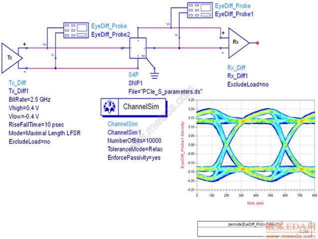
PCI Express Channel Simulation
�Ŵ�
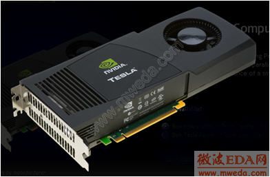
Tesla C1060 GPU Accelerator from NVIDIA
�Ŵ�
Accelerated Transient Simulation with Graphics Processor and Multi-Threading
Using graphics processor to accelerate simulation enables faster co-design verification. In ADS 2009, the transient simulator can take advantage of Nvidia��s latest generation of the Tesla GPU (graphics processing unit) to gain a 4x speed improvement; and along with the multi-threaded convolution simulator, it makes high-speed co-design a reality.
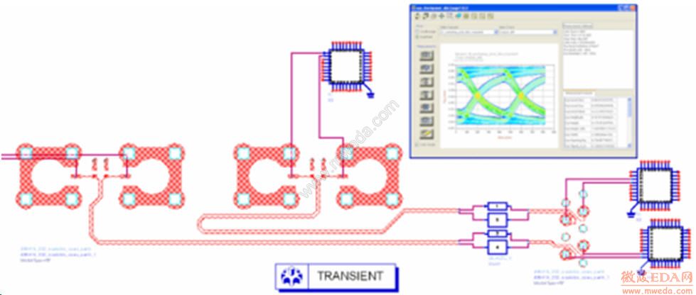
Jitter analysis with instrument-grade eye diagram algorithm
RF Simulation Advancements in ADS 2009 for Co-Design
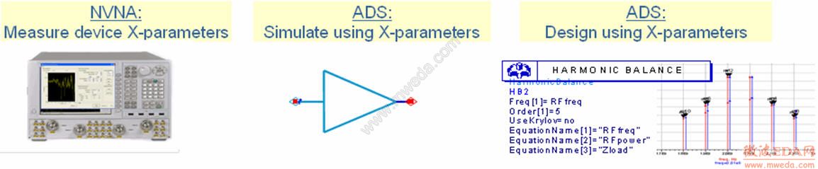
RF simulation advancements in ADS 2009 include co-design with accurate, non-linear X-parameter models from measurement, using Agilent��s non-linear vector network analyzer (NVNA). In the following image, the graphics on the right show the simulated versus measured load-pull power and power-added-efficiency (PAE) contours of the X-parameter power amplifier model demonstrating its validity over a wide range of impedances.
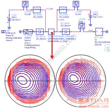
Simulated versus measured power contours (left) and PAE countours (right) with X-parameters
Other enhancements include 2x simulation speedup with multi-threaded harmonic balance simulator and compatibility with HSPICE and Spectre netlist defined sources and components for co-design, along with comprehensive passive interconnect circuit synthesis for stripline and suspended stripline components. The latest wireless standards revision to WiMedia and 3GPP LTE are also included to ensure instrument-grade system verification completeness and accuracy.
Co-Design with X-parameter Models
X-parameters models from non-linear measurement with Agilent��s latest Non-linear Vector Network Analyzer (NVNA) it allows off-the-shelf non-linear components such as power amplifiers or power transistors to be directly measured and used within a wireless system co-design. In the past, the lack of convenient non-linear models of available hardware prevented system co-design. X-parameters are the non-linear superset of linear S-parameters and can be cascaded even with impedance mismatches to predict accurate frequency mixing and harmonics.
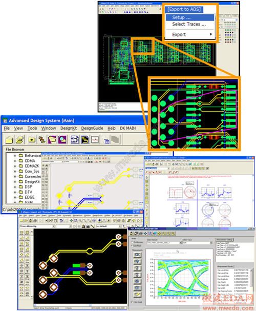
Interoperability with Cadence Allegro Back-end Design Flow for PCB, Package, and Module Co-Design
ADS 2009 interoperates with Cadence Allegro backend design tools - Allegro PCB, Allegro Advanced Package Designer (APD), and Allegro System-in-Package (SiP) - to enable physical design to be conveniently transferred into ADS for co-design with active components for optimal high-frequency and high-speed performance.
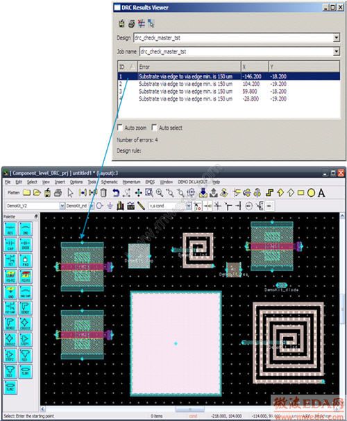
Interoperability with Cadence and Mentor DRC allows ADS 2009 to Fix DRC Errors Locally
ADS 2009 interoperability with Cadence and Mentor back-end design flows extends to MMIC and RFIC design rule checking. DRC violations reported by Cadence Assura or Mentor Calibre or Triquint foundry MailDRC can be directly read and fixed in ADS 2009 layout to provide a cost effective MMIC or RFIC layout solution that can also be incorporated with the rest of the ADS 2009 co-design methodology.
-
������ȫ���ADS��ѵ�̳̣�ȫ�潲����ADS������Ƶ��·��ͨ��ϵͳ�͵�ŷ�����Ʒ�������ݣ���Ƶ�̳̣�ֱ����ѧ��ר�ҽ��⣬����ʵ����ǿ����������̵�ʱ��ѧ��ADS...����ϸ������
- �� Advanced Design System--ADS�����������Ľ̡�
- �� ����ѧ��ADS2011��ADS2012 ���� ������Ƶ�
- �� ADS layout�������������뵽��·���汨������
- �� ��ADS���LC��ͨ�˲���
- �� ADS Momentum��ŷ�����ơ�������Ƶ��ѵ�̡�
- �� ADS2008��װ���⣨������
- �� Agilent AMDS ���߽�ģ�������
- �� ADS�е�е��ݵ�ʵ��ģ��Qֵһ����ôȡ��
- �� ADS����Ƶ��·������ƻ���������Ƶ�̳�
- �� ������ģ����ô����
- �� ���ʴ��ADS2008��PIN����������趨��
- �� ADS2009�����������Ľ̳�
- �� Advanced Design System Ӣ����Ƶ�̳�
- �� ADS2009�����������Ľ̳�
- �� ����Ƶ��·�����ADSʵ����̨�彻��
- �� ADS RFIC���ʵ��γ̽��壨̨�彻ͨ��ѧ��
- Advanced Design System Ӣ����Ƶ�̳�
��ͨ�˲�����ADS�������
ADS�����ļ���ʽ| ADS2009��ADS2008
ADS Momentum���ƽ������ʵ��
ADS2006A��������
Advanced Design System--ADS�����������Ľ̡�
ADS Momentum��ŷ��湤���| ADS2009, A��
ADS2009, ADS2008���ܸ���
Agilent ADS��Ҫ���������� | ADS2009, ADS��
Agilent ADS2009, ADS2008�г��õ������ļ�
���ѧϰ Agilent ADS
ADS Co-simulation with Layout Components
�Ƽ��γ�

-

7��������Ƶ�̳�,2���̲�,��������
-

������Ȩ���������ADS��ѵ�̳���װ
-

��ȫ�������Ƶ���������ѵ�ϼ�
-

����Ansoft Designer������ѵ�̲�
-
ʸ��,Ƶ����,�ź�Դ...,������ͨ
-

��ҵ�����ӽ��ܵĿγ�,ѧ������...
-

ҵ���ţLes Besser����ѵ�γ�...
-

Allegro,PADS,PCB���,��ʵ�ܼ�..
-

Hyperlynx,SIwave,������SI����
-

�ֳ�����,ʵʱ����,����ѧϰ������