
ADS Momentum 仿真设计流程(英文)
05-08
Momentum commands are available from the Layout window. The following steps describe a typical process for creating and simulating a design with Momentum: 1. Create a physical design. You start with the physical dimensions of a planar design, such as a patch antenna or the traces on a multilayer printed circuit board. There are three ways to enter a design into Advanced Design System:
Convert a schematic into a physical layout
Draw the design using Layout
Import a layout from another simulator or design system. Advanced Design System can import files in a variety of formats.
2. Choose Momentum or Momentum RF mode. Momentum can operate in two simulation modes: microwave or RF. You can select the mode based on your design goals. Use Momentum (microwave) mode for designs requiring full-wave electromagnetic simulations that include microwave radiation effects. Use Momentum RF mode for designs that are geometrically complex, electrically small, and do not radiate. You might also choose Momentum RF mode for quick simulations on new microwave models that can ignore radiation effects, and to conserve computer resources.
3. Define the substrate characteristics. A substrate is the media upon which the circuit resides. For example, a multilayer PC board consists of various layers of metal, insulating or dielectric material, and ground planes. Other designs may include covers, or they may be open and radiate into air. A complete substrate definition is required in order to simulate a design. The substrate definition includes the number of layers in the substrate and the composition of each layer. This is also where you position the layers of your physical design within the substrate, and specify the metal characteristics of these layers.
4. Solve the substrate. Momentum calculates the Green's functions that characterize the substrate for a specified frequency range. These calculations are stored in a database, and used later on in the simulation process.
5. Assign port properties. Ports enable you to inject energy into a circuit, which is necessary in order to analyze the behavior of your circuit. You apply ports to a circuit when you create the circuit, and then assign port properties in Momentum. There are several different types of ports that you can use in your circuit, depending on your application.
6. Add a box or a waveguide. These elements enable you to specify boundaries on substrates along the horizontal plane. Without a box or waveguide, the substrate is treated as being infinitely long in the horizontal direction. This treatment is acceptable for many designs, but there may be instances where a boundaries need to be taken into account during the simulation process. A box specifies the boundaries as four perpendicular, vertical walls that make a box around the substrate. A waveguide specifies two vertical walls that cut two sides of the substrate.
7. Create Momentum components. Momentum components can be used in the schematic design environment in combination with all the standard ADS active and passive components to build and simulate circuits including the parasitic layout effects. The Momentum engine is automatically invoked to generate an S-parameter model for the Momentum component during the circuit simulation.
8. Set up and generate a circuit mesh. A mesh is a pattern of rectangles and triangles that is applied to a design in order to break down (discretize) the design into small cells. A mesh is required in order to simulate the design effectively. You can specify a variety of mesh parameters to customize the mesh to your design, or use default values and let Momentum generate an optimal mesh automatically.
9. Simulate the circuit. You set up a simulation by specifying the parameters of a frequency plan, such as the frequency range of the simulation and the sweep type. When the setup is complete, you run the simulation. The simulation process uses the Green's functions computed for the substrate, plus the mesh pattern, and the currents in the design are calculated. S-parameters are then computed based on the currents. If the Adaptive Frequency Sample sweep type is chosen, a fast, accurate simulation is generated, based on a rational fit model.
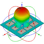
10. View the results. The data from an Momentum simulation is saved as S-parameters or as fields. Use the Data Display or Visualization to view S-parameters and far-field radiation patterns.
Convert a schematic into a physical layout
Draw the design using Layout
Import a layout from another simulator or design system. Advanced Design System can import files in a variety of formats.
2. Choose Momentum or Momentum RF mode. Momentum can operate in two simulation modes: microwave or RF. You can select the mode based on your design goals. Use Momentum (microwave) mode for designs requiring full-wave electromagnetic simulations that include microwave radiation effects. Use Momentum RF mode for designs that are geometrically complex, electrically small, and do not radiate. You might also choose Momentum RF mode for quick simulations on new microwave models that can ignore radiation effects, and to conserve computer resources.
3. Define the substrate characteristics. A substrate is the media upon which the circuit resides. For example, a multilayer PC board consists of various layers of metal, insulating or dielectric material, and ground planes. Other designs may include covers, or they may be open and radiate into air. A complete substrate definition is required in order to simulate a design. The substrate definition includes the number of layers in the substrate and the composition of each layer. This is also where you position the layers of your physical design within the substrate, and specify the metal characteristics of these layers.
4. Solve the substrate. Momentum calculates the Green's functions that characterize the substrate for a specified frequency range. These calculations are stored in a database, and used later on in the simulation process.
5. Assign port properties. Ports enable you to inject energy into a circuit, which is necessary in order to analyze the behavior of your circuit. You apply ports to a circuit when you create the circuit, and then assign port properties in Momentum. There are several different types of ports that you can use in your circuit, depending on your application.
6. Add a box or a waveguide. These elements enable you to specify boundaries on substrates along the horizontal plane. Without a box or waveguide, the substrate is treated as being infinitely long in the horizontal direction. This treatment is acceptable for many designs, but there may be instances where a boundaries need to be taken into account during the simulation process. A box specifies the boundaries as four perpendicular, vertical walls that make a box around the substrate. A waveguide specifies two vertical walls that cut two sides of the substrate.
7. Create Momentum components. Momentum components can be used in the schematic design environment in combination with all the standard ADS active and passive components to build and simulate circuits including the parasitic layout effects. The Momentum engine is automatically invoked to generate an S-parameter model for the Momentum component during the circuit simulation.
8. Set up and generate a circuit mesh. A mesh is a pattern of rectangles and triangles that is applied to a design in order to break down (discretize) the design into small cells. A mesh is required in order to simulate the design effectively. You can specify a variety of mesh parameters to customize the mesh to your design, or use default values and let Momentum generate an optimal mesh automatically.
9. Simulate the circuit. You set up a simulation by specifying the parameters of a frequency plan, such as the frequency range of the simulation and the sweep type. When the setup is complete, you run the simulation. The simulation process uses the Green's functions computed for the substrate, plus the mesh pattern, and the currents in the design are calculated. S-parameters are then computed based on the currents. If the Adaptive Frequency Sample sweep type is chosen, a fast, accurate simulation is generated, based on a rational fit model.
10. View the results. The data from an Momentum simulation is saved as S-parameters or as fields. Use the Data Display or Visualization to view S-parameters and far-field radiation patterns.
相关文章:
- 仿真软件官方网址(05-08)
- 软件中的耦合问题仿真(05-08)
- 请高手看看这几个错误,你们在仿真过程遇到没有啊,请指教谢谢!(05-08)
- 仿真时在30GHz, lumped port 问题(05-08)
- 仿真时出现的问题,请教大家!(05-08)
- 哪位大哥有ADS关于磁场仿真的软件的信息啊?!(05-08)
射频专业培训教程推荐