|
 Ansoft Designer / Ansys Designer 在线帮助文档: Ansoft Designer / Ansys Designer 在线帮助文档:
System Simulator >
System Component Models >
Coders/Decoders >
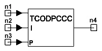
Turbo Coder with PCCC (TCODPCCC)
Turbo Coder with PCCC (TCODPCCC)
Limits:


Notes
1. This model is used for Turbo Coder with Parallel
Concatenated Convolutional Code (PCCC). Kis number of information bits
in each code block
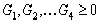
2. Turbo Coder Structure: Fig.1 shows the
diagram of Turbo Coder with PCCC. The encoder consists of two recursive
systematic convolutional (RSC) encoders with rate 1/2 which are separated
by an K-bit interleaver, together with an optional puncturing procedure.
Clearly, without the puncturer, the encoder is rate 1/3, mapping
Kdata bits to 3K code bits. In the K-bit interleaver, denote by i
the index of the input sequence before interleaving and f(t)
is the index of output sequence after interleaving, the interleaving
pattern sequence is given by f(0) f(1) ... f(K-1) .
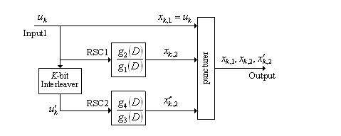
Fig.1 Turbo Coder with PCCC

Fig.2 Recursive Systematic Convolutional (RSC) Encoder
with  , , 
3. RSC Encoder: The RSC code with rate 1/2
has the generator matrix
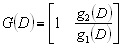 (1) (1)
In the above equation, the polynomials g1(D)
and g2(D are given by
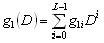  (2) (2)
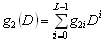  (3) (3)
with L is the constraint length of the RSC code. In this model, g1(D)
and g2(D) are expressed in octal form
G1(D) and G2(D), respectively. For example, if
G1(D) = 1 + D + D4 and
G2(D) = 1 + D2
+ D3 + D4, the octal
forms are G1 = 31, G2
= 27, as shown in Fig.2.
4. When Puncturing is set to 0, no puncturing
is considered. Otherwise, some output bits are deleted according to
a chosen puncturing pattern from the third input port. The number of
bits in the puncturing pattern is called puncturing length. If the element
of the pattern is 1, the corresponding output bit is transmitted.
If the element of the pattern is 0, the corresponding output bit is
omitted.
5. In this model, we can choose whether termination
of each RSC encoder to the zero state or not. The termination method
can be found in [2], as shown in Fig.2. For each RSC encoder, L-1
bits are needed for termination, with L is the constraint length
of the RSC code. Therefore, without the puncturer, we set Termination
to 3, the number of output bits is given by
 (4) (4)
with L1 and L2 is
the constraint length of the first RSC code and of the second RSC code,
respectively.
6. If Out_Type is set to 0, the output of
the true value and the false value are 1 and 0, respectively. If Out_Type
is set to 1, the output of the true value and the false value are 1
and -1, respectively.
Netlist Form:
TCODPCCC:NAME n1 n2 n3 n4 K=val L1=val
L2=val G1=val G2=val G3=val G4=val
[PUNCTURING=val]
+ [TERMINATION =val] [OUT_TYPE =val]
[RIN1=val] [RIN2=val] [RIN3=val] [ROUT=val]
Netlist Example
TCODPCCC:1 1 2 3 4 K=636 L1=5 L2=5 G1=19 G2=31
G3=19 G4=31 PUNCTURING=6 +TERMINATION=3 OUT_TYPE=1
References
1. C. Berrou and A. Glavieux, “Near optimum
error correcting coding and decoding: Turbo-codes,” IEEE Trans.
Commun., vol. 44, no. 10, pp. 1261–1271, 1996.
D. Divsalar and F. Pollara, “Turbo codes for PCS
applications,” Proc. 1995 Int. Conf. Comm., pp54-59.


HFSS视频教程
ADS视频教程
CST视频教程
Ansoft Designer 中文教程
|
|