|
微波射频仿真设计 |
|
|
微波射频仿真设计 |
|
| 首页 >> Ansoft Designer >> Ansoft Designer在线帮助文档 |
|
System Simulator > SL Offset Coupled Lines, Electrical Length (SLOCLE)
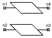
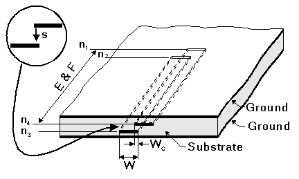
Notes1. The following conditions should be satisfied: -2.5 < WC/B £ W/B, and W/(B-S) ³ 0.35, where B is the ground plane spacing defined in the .SUB statement. 2. The results may not converge for all values of WC/B. 3. If WC/W is larger than or equal to 0.9, the conductor loss attenuation factors (AE and AO) are estimated by the program, unless the user specifies them in the input. 4. If WC/W is less than 0.9, the user has to define AE and AO if their effect is to be taken into consideration. They are not calculated by the program. 5. Metallization thickness is taken into account in the analysis. Netlist FormSLOCLE:NAME n1 n2 n3 n4 W=val S=val
WC=val Netlist ExampleSLOCLE:OCLE2 1 2 3 4 W=50MIL S=40MIL WC=10MIL E=45
F=750MHZ where SUB1 needs to be defined in the corresponding .SUB statement. References1. J. P. Shelton, “Impedances of Offset Parallel Coupled Strip Transmission Line,” IEEE Trans. on MTT, Jan. 1966, pp. 7-15, and correction in MTT, May 1966, p. 249.
HFSS视频教程 ADS视频教程 CST视频教程 Ansoft Designer 中文教程 |
|
Copyright © 2006 - 2013 微波EDA网, All Rights Reserved 业务联系:mweda@163.com |
|


