淘宝官方店     推荐课程     在线工具     联系方式     关于我们  


微波射频仿真设计   Ansoft Designer 中文培训教程   |   HFSS视频培训教程套装


Agilent ADS 视频培训教程   |   CST微波工作室视频教程   |   AWR Microwave Office

          首页 >> Ansoft Designer >> Ansoft Designer在线帮助文档


Ansoft Designer / Ansys Designer 在线帮助文档:


System Simulator >
System Component Models >
Stripline >
   SL Coupled Lines (SLMCPLn, where n is the number of lines)       

SL Coupled Lines (SLMCPLn, where n is the number of lines)


[spacer]

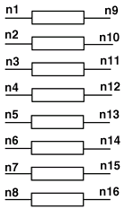
Schematic Symbol Example

(n = 8, SLMCPL8)
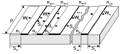
 

[spacer]


Properties

Description

Units

Default

Range

NL

Number of lines

none

Required

[1,20]

W1

Width of line 1

m

Required

> 0

W2 ¼Wm

Widths of line 2 through line NL. Line widths must be numbered consecutively.

m

0.0

³ 0

S1, S2…Sm-1

Line spacing, where Si is the spacing between line i and line i+1, i<NL.

m

0.0

³ 0

S0

Spacing from the left enclosure wall to the first line

m

NL=1:

50´W1

NL>1:

50´ (Wmax+Smax)

³ 0

Sn

Spacing from right enclosure wall to the NLth line.

m

NL=1:

50´W1

NL>1:

30´ (Wmax+Smax)

³0

P

Physical length of the lines

m

Required


Discretization

Discretization type (equidistant or non-equidistant)

none

NonUniform

[Uniform,

NonUniform]

Density

Density of discretization

none

0

³0

Type

Wall type

none

EE

[EE, ME, EM, MM]

label

Substrate name

none

Required

string


Notes

1. Only the quasi-static formulation is available.

2. The numbering of the line widths and spacings must be consecutive, e.g., “MCPL 1 2 3 4… W1=val S1=val W3=val SUB ...” is not allowed because W2 and S2 are missing.

3. The left and right wall types include EE (electric-electric,) ME (magnetic-electric,) EM (elec­tric-magnetic,) and MM (magnetic-magnetic).

4. The default value for S0 and/or SN is 5x(1/2B), where B is the ground planes spacing of the stripline.

5. If the Density parameter is not set, or is set to zero, a value for Density is calculated based on the structure. For example, a higher density (uniform or non-uniform) is required for smaller metal or separation widths.

Netlist Form

SLMCPL:NAME n1 n2 [ n3 ] [ n4 ] [ n40 ]
+ NL=val W1=val [S1=val] [W2=val] [S2=val] [W3=val] [S3=val]
+ [W4=val] … [S0=val] [SN=val] P=val
+ [DISCRETIZATION=val] [DENSITY=val] [TYPE=val] sub=label

Netlist Example (10 coupled striplines)

SLMCPL:MCPL1 1 2 3 4 5 6 7 8 9 10 11 12 13 14 15 16 17 18 19 20
+ NL=10 W1=0.3MM S1=0.3MM W2=0.3MM S2=0.15MM W3=0.2MM S3=0.4MM
+ W4=0.3MM S4=0.2MM W5=0.1MM S5=0.1MM W6=0.2MM S6=0.15MM
+ W7=0.8MM S7=0.3MM W8=0.1MM S8=0.1MM W9=0.5MM S9=0.5MM
+ W10=0.5MM P=20MM S0=10MM SN=5MM SUB=SUB1

where SUB1 needs to be defined in the corresponding .SUB statement.

References


HFSS视频教学培训教程 ADS2011视频培训教程 CST微波工作室教程 Ansoft Designer 教程

                HFSS视频教程                                      ADS视频教程                               CST视频教程                           Ansoft Designer 中文教程


      Copyright © 2006 - 2013   微波EDA网, All Rights Reserved    业务联系:mweda@163.com