|
微波射频仿真设计 |
|
|
微波射频仿真设计 |
|
| 首页 >> Ansoft Designer >> Ansoft Designer在线帮助文档 |
|
System Simulator > SL Compensated Tee Junction (SLCTEE)
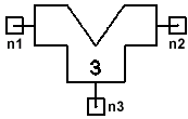
Notes1. This model is available for Planar EM simulation only. 2. The notch angle coincides with the center of the line on port 3. 3. The structure is de-embedded to the reference planes that coincide with the edges of W and W3, respectively, unless the notch angle or depth is such that the edges of the notch fall outside the rectangle transcribed by the physical dimensions W and W3. In that case, the reference planes are transferred to the outermost corners of the notch (see figure.) 4. If a substrate is not defined for the component, the Layout stackup or the Footprint stackup may be used. Netlist FormThere is no netlist form for this component; it is available for Planar EM analysis only. Netlist ExampleN/A
HFSS视频教程 ADS视频教程 CST视频教程 Ansoft Designer 中文教程 |
|
Copyright © 2006 - 2013 微波EDA网, All Rights Reserved 业务联系:mweda@163.com |
|


