|
微波射频仿真设计 |
|
|
微波射频仿真设计 |
|
| 首页 >> Ansoft Designer >> Ansoft Designer在线帮助文档 |
|
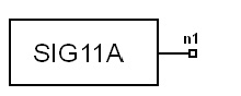
System Simulator > Signal Field Bits Generator, 802.11a (SIG11A)
Limits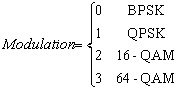
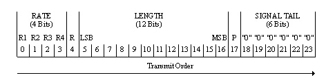
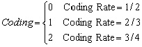 Notes1. This model can be used to generate the contents of the SIGNAL field, according to IEEE 802.11a standard. 2. The SIGNAL field contains the RATE and the LENGTH fields. The RATE field conveys information about the type of modulation and the coding rate as used in the rest of the packet. The encoding of the SIGNAL single OFDM symbol shall be performed with BPSK modulation of the subcarriers and using convolutional coding at R = 1/2. The contents of the SIGNAL field are not scrambled. The SIGNAL field shall be composed of 24 bits, as illustrated in Fig.1. The four bits 0 to 3 shall encode the RATE. Bit 4 shall be reserved for future use. Bits 5~16 shall encode the LENGTH field, with the least significant bit (LSB) being transmitted first. 3. Data rate (RATE): The bits R1~R4 shall be set, dependent on RATE, according to the values in Table I. The data rate is determined by the two parameters, Modulation and Coding, as shown in Table II. 4. PLCP length field (LENGTH): The PLCP length field shall be an unsigned 12-bit integer that indicates the number of octets in the PSDU that the MAC is currently requesting the PHY to transmit. This value is used to determine the number of octet transfers that will occur between the MAC and the PHY after receiving a request to start transmission. The LSB shall be transmitted first in time. 5. Parity (P), Reserved (R), and SIGNAL tail (SIGNAL TAIL): The Bit 4 shall be reserved for future use. Bit 17 shall be a positive parity (even parity) bit for bits 0~16. The bits 18–23 constitute the SIGNAL TAIL field, and all 6 bits shall be set to zero.
Table I Contents of IEEE 802.11a SIGNAL field
Table II IEEE 802.11a Rate-dependent parameter
Netlist FormSIG11A:NAME n1 n2 [MODULATION =val] [CODING
=val] Netlist ExampleSIG11A:1 1 2 MODULATION = 2 CODING= 2 LENGTH = 100 References1. IEEE Std 802.11a, Part 11: “Wireless LAN Medium Access Control (MAC) and Physical Layer (PHY) specifications: High-speed Physical Layer in the 5 GHz Band,” ISO/IEC 8802-11:1999/Amd 1:2000(E).
HFSS视频教程 ADS视频教程 CST视频教程 Ansoft Designer 中文教程 |
||||||||||||||||||||||||||||||||||||||||||||||||||||||||||||||||||||||||||||||||||||||||||||||||||||||||||||||||||
|
Copyright © 2006 - 2013 微波EDA网, All Rights Reserved 业务联系:mweda@163.com |
|
 )
) )
) )
)


