|
微波射频仿真设计 |
|
|
微波射频仿真设计 |
|
| 首页 >> Ansoft Designer >> Ansoft Designer在线帮助文档 |
|
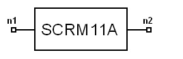
System Simulator > Scrambler, 802.11a (SCRM11A)
Limits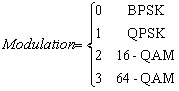
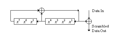
 Notes1. This model can be used to scramble the DATA field and then let the tail bits be zero, according to IEEE 802.11a standard. 2. The DATA field, composed of SERVICE, PSDU, tail,
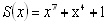
and pad parts, shall be scrambled with a length-127 frame-synchronous
scrambler. The frame synchronous scrambler uses the generator
polynomia S(x)l as follows, and is illustrated in Fig.1. 3. The 6 tail bits should be reset to “zero”.
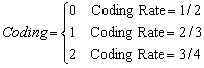
The position of the tail bits can be determined by the three parameters,
Modulation, Coding, and Length. The position of the first tail bit is
determined by:
Fig.1 Data scrambler Netlist FormSCRM11A:NAME n1 n2 [MODULATION =val] [CODING
=val] Netlist ExampleSCRM11A:1 1 2 MODULATION = 2 CODING= 2 LENGTH = 100 S0 = 93 References1. IEEE Std 802.11a, Part 11: “Wireless LAN Medium Access Control (MAC) and Physical Layer (PHY) specifications: High-speed Physical Layer in the 5 GHz Band,” ISO/IEC 8802-11:1999/Amd 1:2000(E).
HFSS视频教程 ADS视频教程 CST视频教程 Ansoft Designer 中文教程 |
||||||||||||||||||||||||||||||||||||||||||||||||||||
|
Copyright © 2006 - 2013 微波EDA网, All Rights Reserved 业务联系:mweda@163.com |
|
 (1)
(1) (2)
(2)