|
微波射频仿真设计 |
|
|
微波射频仿真设计 |
|
| 首页 >> Ansoft Designer >> Ansoft Designer在线帮助文档 |
|
System Simulator > Schmitt Trigger Nonlinear (SCHMIT)
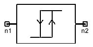
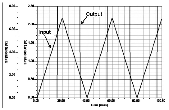
LimitsVIL <= VIH VOL <= VOH Notes1. This element is a Schmitt trigger with programmable levels. The output of this element is always a baseband signal. 2. The input voltage must actually cross the threshold before the output voltage changes. For example, a trigger VIL=0 and VIH=2, whose output is currently the ‘low’ value, will not change its output on the input sequence, 1.7V, 1.8V, 1.9V, 2.0V, 1.9V, etc. 3. The initial value of the output is VOH if the initial input is greater than VIH. The initial value of the output is VOL otherwise. 4. Example: Input and output waveforms are shown for a Schmitt trigger with the following parameters: VIL = 2, VIH = 5.6, VOL = 0, and VOH = 2.5.
Netlist FormSCHMIT:Name n1 n2 VIL=val VIH=val VOL=val VOH=val [Rin=val][Rout=val] Netlist ExampleSCHMIT:1 1 2 VIL=13.5mv VIH=15mv VOL=0 VOH=1
HFSS视频教程 ADS视频教程 CST视频教程 Ansoft Designer 中文教程 |
||||||||||||||||||||||||||||||||||||||||||||||||||||
|
Copyright © 2006 - 2013 微波EDA网, All Rights Reserved 业务联系:mweda@163.com |
|