|
 Ansoft Designer / Ansys Designer 在线帮助文档: Ansoft Designer / Ansys Designer 在线帮助文档:
System Simulator >
System Component Models >
Coders/Decoders >
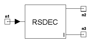
Reed-Solomon Decoder (RSDEC)
Reed-Solomon Decoder (RSDEC)
Limits


Notes
This model is used to perform Reed-Solomon (RS) decoding.
A systematic RS(n,k) code, which is defined on Galois Field
(2m), consists of k input data symbols
and (n-k) parity code symbols. For details about RS coding, please
refer to the rscod model. A general architecture for RS decoder
is shown in Fig.1
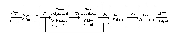
Fig.1: Codeword for systematic Reed-Solomon coder
r(x) Received codeword
bl Error locations
Si Syndromes
eji Error values
s(X) Error location polynomial
c(x) Corrected codeword
A Reed-Solomon decoder attempts to identify the positions and values
of up to
t = (n-k)/2 errors and then correct the errors. In case of shortened
codes, the appropriate sequence of zero-padding is first rebuilt so
that the codeword is equal to 2m-1.
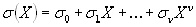
Let v(x) be the transmitted code vector,
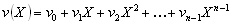 (1) (1)
and r(x) be the corresponding received vector,
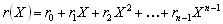 (2) (2)
The error pattern, e(X) ,is added by the channel,
 (3) (3)
where e(X) is an element from GF(2m). Considering
the number of elements, n, in the error pattern,
e(X), at the location Xj1,Xj2
, …,Xjn
with 0<= jn <= n-1, we have
 (4) (4)
Explanation of decoding process for RS codes:
(1) Syndrome Calculation
A Reed-Solomon codeword has 2t syndromes,
which can be calculated by substituting the 2t roots of the generator
polynomial g(X) into r(X), i.e., Si
= r(ab0 +i -1),
where i= 1,2,...2t.
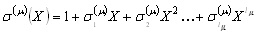
(2) Determination of the error-location polynomial
The syndromes are used to find the error-location
polynomial. The error location polynomial is defined as
 (5) (5)
The error location polynomial has n roots,
the inverses of which indicate the error locations. s(X)
is an undetermined polynomial and its coefficients must be determined.
The Berlekamp’s iterative algoithm is used to construct this polynomial,
which is the key to RS decoding.
Now we consider the minimum degree polynomial determined at the m-th step of iteration.
 (6) (6)
where lm is the degree
of s(m)(X)
To determine s(μ+1)(X),
we compute the following quantity:
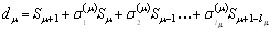 (7) (7)
This quantity dm is called the
m-th discrepancy.
To carry out the iteration of finding s(X),
we begin with Table I and proceed to fill out this table. Assuming
that we have filled out all rows up to and including theC
row, we fill out the μ+1-th row as follows:
(a) If dm= 0, then s(μ+1)(X)
= s(m)(X)
and lμ+1 = lm
(b) If dμ is
not equal to 0, find another row,r, prior
to the m-th row such that dr
does not equal zero, and the number r-lr in the last column of the table
has the largest value. Then, s(μ+1)(X) is given by
the following two equations:
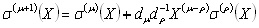 (8) and (8) and
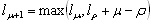 (9) (9)
And for both cases:
 (10) (10)
Rows in this table after the first two are generated by iteratively
applying the equations given above.
If the order of the polynomial is greater
than t, which means the received codeword has more than t
errors, the errors cannot be corrected and the received vector r(X)
is output as is, error indicator is set to -1. Otherwise, error indicator
is the number of errors.
(3) Determination of the error-location numbers
The error location numbers bl
(1<= l <= m) are the inverses of the
roots of s(X). The roots of s(x) can be found simply by substituting
1, α, α2, ...αn−1 (n = 2m-1)
into s(X). Therefore, if al is a root of s(X),
a(n-l) is an error location
number and the received rn-l is an error symbol.
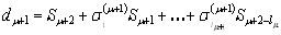
(4) Calculation of the error values and correcting
the received codeword
The error value at location bl
= ajl is calculated
based on the following equation:
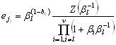 (11) (11)
where
 (12) (12)
Finally, the decoding procedure is completed by the subtraction of the
received vector r(X) and the error vector e(X).
Netlist Form
RSDEC:NAME n1 n2 n3 N=val K=val M
=val [B0 =val] [P0=val . . . PM=val] +[RIN=val]
[ROUT1=val] [ROUT2=val]
Netlist Example
RSDEC:1 1 2 3 N=204 K=188 M =8 B0 =1 {P0,…P8}
= {1,0,1,1,1,0,0,0,1}
References
1. Shu Lin and D.J.Costello, Error Control Coding:
Fundamentals and applications, Prentice-Hall, 1983.
2. Elwyn Berlekamp, Algebraic Coding Theory, McGraw-Hill,
New York, 1968.
3. Y.Shayan, T.Le-Ngoc and V.Bhargava, “A
versatile time-domain Reed-Solomon decoder,” IEEE Journal
on Selected Areas in Communications, vol. 8, No.8, pp.1535-1542,
Oct. 1990.


HFSS视频教程
ADS视频教程
CST视频教程
Ansoft Designer 中文教程
|
|