|
微波射频仿真设计 |
|
|
微波射频仿真设计 |
|
| 首页 >> Ansoft Designer >> Ansoft Designer在线帮助文档 |
|
System Simulator > RLSE DFE Equalizer
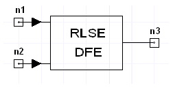 RLSE DFE Netlist FormatThe RLSE DFE is inserted across a differential line pair to tell transient analysis to generate an eye diagram for the equalized signal at the associated signal probe. Equalization uses the recursive least squares (RLS) algorithm (see Notes). ARLSE_DFE:xxxx n1 n2
n3 n1 is the positive node and n2 is the negative node of the differential line pair. The entry COMPONENT=rlse_dfe identifies the component.
DFE Equalizer Netlist ExampleARLSE_DFE:2 net_1 net_2 net_3 NotesA decision-feedback equalizer (DFE) is a non-linear equalizer containing a feed-forward filter and a feed-back filter. For a feed-forward equalizer, the feed-back portion is eliminated. A training signal must be provided to allow the equalizer to calculate the initial tap weights. Here is the architecture of a DFE with N weights, where the symbol period is T.
Recursive Least Squares Algorithm This model updates the filter coefficients of the equalizer based on the input signal and the error signal (i.e., the difference between the output of the equalizer and the actual desired output). The update is based on the recursive least square algorithm [1], [2]. Let X(n) and h(n) denote the input signal vector and the vector of the real filter coefficients respectively at time instant n. Each vector is assumed to be of length NTAPS, the combined number of feed-forward and feed-back filter taps (NTAPS = FF_TAPS + FB_TAPS). In addition, let K(n) denote the NTAPS x 1 Kalman gain vector and let P(n) denote the NTAPS x NTAPS inverse of the correlation matrix of the input signal. The recursive least square algorithm is given by the following five steps: 1. Compute the filter output: y(n) = tran(X(n)) * h(n-1) 2. Compute the error: e(n) = d(n) - y(n), where d(n) is the desired output 3. Compute the NTAPS x 1 Kalman gain vector: K(n) = [P(n-1) * X(n)]/[LAMBDA + tran(X(n)) * P(n-1) * X(n)] 4. Update the inverse of the correlation matrix: P(n) = (1/LAMBDA) [P(n-1) - K(n) * tran(X(n)) * P(n-1)] 5. Update the coefficients of the filter: h(n) = h(n-1) + K(n) * e(n) The following initial conditions are always assumed: 1. P(-1) = (1/DELTA) * I, where DELTA is a small positive number and I is the NTAPS x NTAPS identity matrix, 2. e(-1) = 0 3. h(-1) = 0. Schematic Configuration for Transient AnalysisFor Transient analysis, the schematic includes the RLS equalizer, samplers to convert the real signals to symbols, and a system probe to generate the eye diagram:
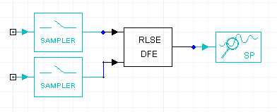 The SAMPLE_RATE for both samplers is (1 / UI). References1. J. G. Proakis, Digital Communications, McGraw-Hill, 1989. 2. J. G. Proakis and D. G. Manolakis, Digital Signal Processing, Macmillan, 1988.
HFSS视频教程 ADS视频教程 CST视频教程 Ansoft Designer 中文教程 |
|
Copyright © 2006 - 2013 微波EDA网, All Rights Reserved 业务联系:mweda@163.com |
|


