|
微波射频仿真设计 |
|
|
微波射频仿真设计 |
|
| 首页 >> Ansoft Designer >> Ansoft Designer在线帮助文档 |
|
System Simulator > Raised Cosine Low Pass Filter (RCLPF)
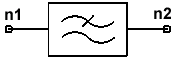
Notes1. The raised cosine frequency characteristic is given by: where B is the rolloff factor, and takes values ranging from 0 to 1. 2. The bandwidth occupied by the signal beyond the cutoff frequency FC is called the excess bandwidth and is usually expressed as a percentage of the cutoff frequency. For example, when B=0.5, the excess bandwidth is 50%, and when B=1.0, the excess bandwidth is 100%. 3. The exponential parameter E raises the transfer function to the power E: HFRC(jw)=(HRC(jw))E. The default value E=0.5 is typically used in a cascade of identical transmit and receive filters. 4. At DC, the filter is implemented as a short circuit. Netlist FormRCLPF:NAME n1 n2 FC=val [B=val] [E=val] Netlist ExampleRCLPF:1 1 2 FC=2GHZ B=1 e=1 References1. G. Proakis, Digital Communications, McGraw-Hill, 1989
HFSS视频教程 ADS视频教程 CST视频教程 Ansoft Designer 中文教程 |
|
Copyright © 2006 - 2013 微波EDA网, All Rights Reserved 业务联系:mweda@163.com |
|


