淘宝官方店     推荐课程     在线工具     联系方式     关于我们  


微波射频仿真设计   Ansoft Designer 中文培训教程   |   HFSS视频培训教程套装


Agilent ADS 视频培训教程   |   CST微波工作室视频教程   |   AWR Microwave Office

          首页 >> Ansoft Designer >> Ansoft Designer在线帮助文档


Ansoft Designer / Ansys Designer 在线帮助文档:


System Simulator >
System Component Models >
Ideal Microwave  >
   Power Combiner/Divider, 2-Way (PWCMB2)       
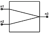
Power Combiner/Divider, 2-Way (PWCMB2)


[spacer]


Properties

Description

Units

Default

Range

L13

Insertion loss between port 1 and port 3

dB

3.0104

[3.0104,INF)

PH13

Phase shift between port 1 and port 3

Angle

-90

(-INF,INF)

IL23

Insertion loss between port 2 and port 3

dB

3.0104

[3.0104,INF)

PH23

Phase shift between port 2 and port 3


-90

(-INF,INF)

RO

Reference Impedance

Ohm

50

(0,INF)


Notes

1. |S13| = |S23| = |S31| = |S32| = -3dB

2. S11=S22=S33=S21=S12=0

3. The phases of all S parameters are zero.

4. All the parameters are assumed to be constant. If not, the frequency and/or temperature depen­dent S-parameters, ABCD-parameters, Z-parameters or Y-parameters should be measured /calculated, stored in an external file, and referred to from the element’s property window. For more information see the Data Format chapter of this manual.

Netlist Form

PWCMB2:NAME n1 n2 n3 [T=val]

Netlist Example

PWCMB2:1 1 2 3

References


HFSS视频教学培训教程 ADS2011视频培训教程 CST微波工作室教程 Ansoft Designer 教程

                HFSS视频教程                                      ADS视频教程                               CST视频教程                           Ansoft Designer 中文教程


      Copyright © 2006 - 2013   微波EDA网, All Rights Reserved    业务联系:mweda@163.com