|
微波射频仿真设计 |
|
|
微波射频仿真设计 |
|
| 首页 >> Ansoft Designer >> Ansoft Designer在线帮助文档 |
|
System Simulator > Phase Shift Keying Demodulator (PSKDEM)
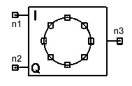
Notes1. This model maps each pair of samples (one from each input signal) into one symbol k, where k is in the Range/Type 0,...., M - 1. This model is normally used in conjunction with the model PSKMOD (Phase Shift Keying Modulator). The symbol which corresponds to the minimum Euclidean distance from the received complex symbol is written to the output. Netlist FormPSKDEM:Name n1 n2 n3 M=val [Ri1=val] [Rin2=val] [Rout=val] Netlist ExamplePSKDEM:1 1 2 3 M=4
HFSS视频教程 ADS视频教程 CST视频教程 Ansoft Designer 中文教程 |
|||||||||||||||||||||||||||||||||||||||||||||||
|
Copyright © 2006 - 2013 微波EDA网, All Rights Reserved 业务联系:mweda@163.com |
|


