|
微波射频仿真设计 |
|
|
微波射频仿真设计 |
|
| 首页 >> Ansoft Designer >> Ansoft Designer在线帮助文档 |
|
System Simulator > Periodic Binary Bits Generator, Differential Waveform Outputs (PBGEND)
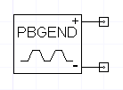
NotesThis model outputs a periodic waveform to the first output defined by the user specified parameters. The second output is simply the negative of the first output. This generated “positive” output waveform is a periodic waveform of T's and F's with a BR bit rate and a TS sampling period. The period of this bit sequence, in bits, is given by PERIOD and the bits generated during each period are specified by BIT_PATTERN in binary format. For example, if BIT_PATTERFN = 1010, PERIOD = 4 bits, BR = 10 bits/sec, TS = 50 ms, then output sequence will be (in samples) F/2F/2T/2T/2F/2F/2T/2T/2F/2F ... . Note that the resulting number of samples per bit in this case is 2 = 1/(TS*BR). Also note that the pattern always starts with the least significant bit of BIT_PATTERN. It is common that the parameters T and F are set to the default values of 1 and 0 respectively. Netlist FormPBGEND:NAME n1 n2 Bit_Pattern=val Period=val [NB=val]
[BR=val] [T=val] [F=val] Netlist ExamplePBGEND:1 1 2 Bit_Pattern=10 Period=6 NB=1024
HFSS视频教程 ADS视频教程 CST视频教程 Ansoft Designer 中文教程 |
|||||||||||||||||||||||||||||||||||||||||||||||||||||||||||||||||||||||||||||||||||||||||||||||||||||||||||
|
Copyright © 2006 - 2013 微波EDA网, All Rights Reserved 业务联系:mweda@163.com |
|


