|
 Ansoft Designer / Ansys Designer 在线帮助文档: Ansoft Designer / Ansys Designer 在线帮助文档:
System Simulator >
System Component Models >
IEEE802dot11a >
Padder, 802.11a (PAD11A)
Padder, 802.11a (PAD11A)
Limits

 Notes
1. This model can be used to form DATA field bits
by prepending the SERVICE field, add tail bits and pad bits, according
to IEEE 802.11a standard.
2. Fig.1 shows the format for the PPDU including
the OFDM PLCP preamble, OFDM PLCP header, PSDU, tail bits, and pad bits.
The PLCP header contains the following fields: LENGTH, RATE, a reserved
bit, an even parity bit, and the SERVICE field. In terms of modulation,
the LENGTH, RATE, reserved bit, and parity bit (with 6 “zero”
tail bits appended) constitute a separate single OFDM symbol, denoted
SIGNAL, which is transmitted with the most robust combination of BPSK
modulation and a coding rate of R=1/2. The SERVICE field of the PLCP
header and the PSDU (with 6 “zero” tail bits and pad bits
appended), denoted as DATA, are transmitted at the data rate described
in the RATE field and may constitute multiple OFDM symbols. The
tail bits in the SIGNAL symbol enable decoding of the RATE and LENGTH
fields immediately after the reception of the tail bits. The RATE and
LENGTH are required for decoding the DATA part of the packet. We will
describe the DATA field in the following sections
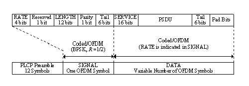
Fig.1 PPDU frame format
3. Service field (SERVICE)
The IEEE 802.11 SERVICE field has 16 bits, which shall be denoted as
bits 0~15, as shown in Fig.2. The bit 0 shall be transmitted first in
time. The bits from 0~6 of the SERVICE field, which are transmitted
first, are set to zeros and are used to synchronize the descrambler
in the receiver. The remaining 9 bits (7~15) of the SERVICE field shall
be reserved for future use. All reserved bits shall be set to zero.
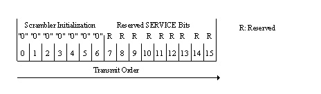
Fig.2 SERVICE field bit assignment
4. Tail bits field (TAIL)
The PPDU tail bits field shall be six bits of “0”, which
are required to return the convolutional encoder to the “zero
state”. This procedure improves the error probability of the convolutional
decoder, which relies on future bits when decoding and which may be
not be available past the end of the message. The PLCP tail bit field
shall be produced by replacing six scrambled “zero” bits
following the message end with six nonscrambled “zero” bits.
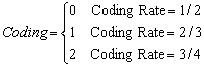
5. Pad bits (PAD)
The number of bits in the DATA field shall be a multiple of NCBPS,
the number of coded bits in an OFDM symbol (48, 96, 192, or 288 bits),
as shown in Table I. To achieve that, the length of the message is extended
so that it becomes a multiple of NDBPS, the number
of data bits per OFDM symbol. NCBPS and NDBPS
can be determined by the two parameters, Modulation and Coding as shown
in Table I. At least 6 bits are appended to the message, in order to
accommodate the TAIL bits. The number of OFDM symbols NSYM
the number of bits in the DATA field NDATA and the
number of pad bits NPAD are computed from the length
of the PSDU (Length) as follows:
 (1) (1)
 (2) (2)
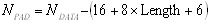 (3) (3)
The function ceiling (.) is a function that returns the smallest integer
value greater than or equal to its argument value. The appended bits
(“pad bits”) are set to “zeros” and are subsequently
scrambled with the rest of the bits in the DATA field.
Table I IEEE 802.11a Rate-dependent parameter
Data rate
(Mbits/s)
|
Modulation
|
Coding rate
(R)
|
Coding bits
per subcarrier
(NBPSC)
|
Coding bits per OFDM symbol
(NCBPS)
|
Data bits
per OFDM
symbol
(NDBPS)
|
6
|
BPSK
|
1/2
|
1
|
48
|
24
|
9
|
BPSK
|
3/4
|
1
|
48
|
36
|
12
|
QPSK
|
1/2
|
2
|
96
|
48
|
18
|
QPSK
|
3/4
|
2
|
96
|
72
|
24
|
16-QAM
|
1/2
|
4
|
192
|
96
|
36
|
16-QAM
|
3/4
|
4
|
192
|
144
|
48
|
64-QAM
|
2/3
|
6
|
288
|
192
|
54
|
64-QAM
|
3/4
|
6
|
288
|
216
|
Netlist Form
PAD11A:NAME n1 n2 [MODULATION =val] [CODING
=val]
+ [LENGTH =val] [RIN=val] [ROUT=val]
Netlist Example
PAD11A:1 1 2 MODULATION = 2 CODING= 2 LENGTH = 100
References
1. IEEE Std 802.11a, Part 11: “Wireless LAN
Medium Access Control (MAC) and Physical Layer (PHY) specifications:
High-speed Physical Layer in the 5 GHz Band,” ISO/IEC 8802-11:1999/Amd
1:2000(E).


HFSS视频教程
ADS视频教程
CST视频教程
Ansoft Designer 中文教程
|
|