|
微波射频仿真设计 |
|
|
微波射频仿真设计 |
|
| 首页 >> Ansoft Designer >> Ansoft Designer在线帮助文档 |
|
System Simulator > MS TEE, Reference Planes at Edge (MSTEEE)
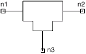
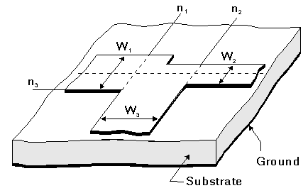
Notes1. To get accurate results, the following condition should be satisfied: H/lg << 1, where lg is the guide wavelength in the substrate dielectric. 2. The collinear lines are connected to nodes n1 and n2 and have widths W1 and W2; the perpendicular line is connected to node n3 and has width W3. 3. Radiation loss is calculated if HU is not specified in the .SUB statement. 4. If W1 > W2: Node n3 is collinear with W1 5. If W2 > W1: Node n3 is collinear with W2. Netlist FormMSTEEE:NAME n1 n2 n3 W1=val W2=val W3=val [NSUM=val] SUB=label Netlist ExampleMSTEEE:TEEE1 1 2 3 W1=32MIL W2=48MIL W3=54MIL SUB=SUB1 where sub1 needs to be defined in the corresponding .sub statement.
HFSS视频教程 ADS视频教程 CST视频教程 Ansoft Designer 中文教程 |
|
Copyright © 2006 - 2013 微波EDA网, All Rights Reserved 业务联系:mweda@163.com |
|


