|
微波射频仿真设计 |
|
|
微波射频仿真设计 |
|
| 首页 >> Ansoft Designer >> Ansoft Designer在线帮助文档 |
|
System Simulator > MS Tee, Reference Planes at Center (MSTEEC)
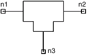
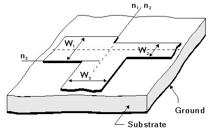
Notes1. To get accurate results, the following condition should be satisfied: H/lg << 1, where lg is the guide wavelength in the substrate dielectric. 2. The collinear lines are connected to nodes n1 and n2 and have widths W1 and W2; the perpendicular line is connected to node n3 and has width W3. 3. The n1, n2 reference plane is centered on the width of the line connected to node n3 (width W3). 4. Radiation loss is calculated if HU is not specified in the .SUB statement. 5. If W1 > W2: Node n3 is collinear with W1. 6. If W2 > W1: Node n3 is collinear with W2. Netlist FormMSTEEC:NAME n1 n2 n3 W1=val W2=val W3=val [NSUM=val] SUB=label Netlist ExampleMSTEEC:TEEC1 1 2 3 W1=32MIL W2=48MIL W3=54MIL SUB=SUB1 where sub1 needs to be defined in the corresponding .sub statement. References
HFSS视频教程 ADS视频教程 CST视频教程 Ansoft Designer 中文教程 |
|
Copyright © 2006 - 2013 微波EDA网, All Rights Reserved 业务联系:mweda@163.com |
|


