淘宝官方店     推荐课程     在线工具     联系方式     关于我们  


微波射频仿真设计   Ansoft Designer 中文培训教程   |   HFSS视频培训教程套装


Agilent ADS 视频培训教程   |   CST微波工作室视频教程   |   AWR Microwave Office

          首页 >> Ansoft Designer >> Ansoft Designer在线帮助文档


Ansoft Designer / Ansys Designer 在线帮助文档:


System Simulator >
System Component Models >
Microstrip >
   MS Coupled Lines (n), Full Wave Model (MSMCPLn)       

MS Coupled Lines (n), Full Wave Model (MSMCPLn)


[spacer]

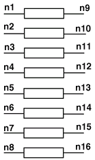
Schematic Symbol Example

(for n = 8, MSMCPL8)
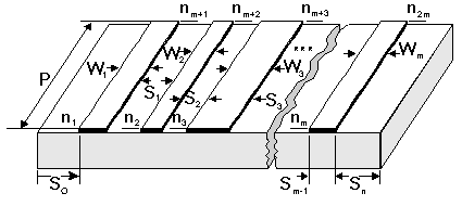
 

[spacer]


Properties

Description

Units

Default

Range

NL

Number of lines.

none

Required

[1,20]

W1

Width of line 1.

m

Required

> 0

W2 ¼Wm

Widths of line 2 through line NL. Line widths must be numbered consecutively.

m

0.0

³ 0

S1, S2…Sm-1

Line spacing, where Si is the spacing between line i and line i+1, NL.

m

0.0

³ 0

S0

Optional spacing from the left enclosure wall to the first line

m

For NL= 1:

50´W1

For NL> 1:

30 ´ (structure width)

> 0

Sn

Optional spacing from right enclosure wall to the NLth line.

m

For NL=1:

50´W1

For NL>1:

30´ (structure width)

> 0

P

Physical length of the lines

m

Required


NBAS

Number of basis functions used in the expansions.

none

3

[1,5]

NSUM

Number of summations to use in the expansions.

none

700

[100,1500]

CERR

Calculation tolerance error (minimum value=1.0E-14)

none

1.0E-7

[1×10-14,1×10-6]

STEP

Root-searching algorithm step size

none

0.01

[1×10-3,0.5]

FO

Optional semi-dynamic mode calculation frequency

Hz

0

³ 0

Simulator

Model selection

none

Full

Wave

[FullWave, SemiDynamic, Quasistatic]

Discretization

Discretization type for quasistatic simulation

none

Non

Uniform

[Uniform, NonUniform]

Density

Density of discretization

none

0

³ 0

Type

Wall type

none

EE

[EE, ME]

label

Substrate name

none

Required

string

CoSimulator

Simulation engine

none


Planar EM

CoSimStackup

Stackup used for simulation

none

Layout Stackup

Layout Stackup, Footprint stackup, Substrate


Notes

1. If the number of lines is greater than 12, default NBAS is set to 1 and default CERR is set to 10.e-10.

2. The component name depends on the number of lines needed. MSMCPL2 for two lines, MSMCPL3 for three lines, etc.

3. There are three available models for the MSMCPL lines, set through the “Simulator” keyword; full wave (FullWave), semi dynamic (SemiDynamic), and quasi static (QuasiStatic). The anal­ysis defaults to full wave if the Simulator parameter is not set.

4. The parameters controlling the specifications of the MSMCPL model are separated into four groups.

* The first group are parameters shared by all the models. These are NL, Wi, Si, Simulator, S0, SN, Type & P.

* The second group are the parameters used only for the full wave solution setup. These are NBAS, NSUM, CERR, and STEP.

* The third group includes only the FO parameter, which is used in the semi dynamic analysis only. If a semi dynamic analysis is set, and FO is not specified, the center frequency of the sweep will be used as FO.
* The fourth group includes the parameters used in the quasi-static analysis only. These are Discretization and Density.

5. The default values for S0 and SN are different, depending on the analysis used:

* In the case of the full wave or the quasi-static calculation, if either S0 or SN is not set, it defaults to:
Single line: S0=Sn=50.0*W
Multi-line: S0=Sn=30.0*(Wmax+ Smax), where Wmax=max(W1,W2,…Wm), Smax=max(S1,S2,, … Sm-1)).

* In the case of the semi dynamic model, if either S0 or SN is not set, it defaults to 5*H (where H is the substrate height.)

6. If the Density parameter is not set, or is set to zero, a value for Density is calculated based on the structure. For example, a higher density (uniform or non-uniform) is required for smaller metal or separation widths.

7. The full wave model uses a proprietary full-wave spectral domain-based algorithm. The parameters CERR, STEP, NBAS, and NSUM are control parameters of the model solver for the full wave and semi dynamic models only. These parameters are assigned default values as shown above. These values have been determined to yield acceptable results for a wide range of input parameters. They should be changed observing spectral domain techniques and machine numerical limitations.

8. The numbering of the line widths and spacings must be consecutive, e.g:
“MSMCPL:MCPL1 1 2 3 4… W1=val S1=val W3=val” is not allowed because W2 and S2 are missing.

9. If there is difficulty finding roots, the default values should be changed as follows:

* NSUM: Gradually increased to 1200 (up to max. of 1500) until roots can be found.
* CERR: Gradually decreased to 10-11 or 10-12 down to minimum of 10-14.
* CERR: Reduce when using more than four lines where the line widths are equal and line spacings are equal.
* S0 and Sn: Reduce from defaults. In the case of multi-line, reduce S0=Sn£10.0´(Wmax+ Smax).
* NSUM: When S0 and Sn are comparable to Wmax or Smax, reduce NSUM to 500 or less.

10. In the semi dynamic mode, the effective dielectric constants and characteristic impedances are computed only once at the frequency FO. If the analysis has been set to semi dynamic, but FO has not been set, it defaults to the center frequency of the sweep. The data calculated at FO is then used to compute the model for all other frequencies. This semi-dynamic mode offers a very fast solution and a close approximation to the full-wave solution. Typically, FO should be specified at the center of the frequency range of interest with values exceeding a 1GHz mini­mum.

Netlist Form

MSMCPL:NAME n1 [n2 n3 n4 … n40]

+ NL=val W1=val [S1=val] [W2=val] [S2=val] [W3=val] [S3=val]
+ [W4=val] [S4=val] … [W19=val] [S19=val] [W20=val]
+ [S0=val] [SN=val] P=val [TYPE=val] [SIMULATOR=val]
+ {[NBAS=val] [CERR=val] [NSUM=val] [STEP=val] |
+ [NBAS=val] [CERR=val] [NSUM=val] [STEP=val] [FO=val] |
+ [DISCRETIZATION=val] [DENSITY=val]} SUB=label

Netlist Example (10 coupled microstrip lines)

MSMCPL:MCPL1 1 2 3 4 5 6 7 8 9 10 11 12 13 14 15 16 17 18 19 20

+ NL=10 W1=0.3MM S1=0.3MM W2=0.3MM S2=0.15MM W3=0.2MM S3=0.4MM
+ W4=0.3MM S4=0.2MM W5=0.1MM S5=0.1MM W6=0.2MM S6=0.15MM
+ W7=0.8MM S7=0.3MM W8=0.1MM S8=0.1MM W9=0.5MM S9=0.5MM
+ W10=0.5MM P=20MM S0=10MM SN=5MM SIMULATOR=SemiDynamic
+ NBAS=3 CERR=2E-6 STEP=0.005 NSUM=600 FO=1.5GHz SUB=SUB1

where sub1 needs to be defined in the corresponding .sub statement.

Netlist Example (20 coupled microstrip lines)

.PARAM SS=40UM
.PARAM WW=40UM
.PARAM L1=3MM
.SUBCKT MCPL20 1 ... 40

MSMCPL:MCPL1 1 2 3 4 5 6 7 8 9 10 11 12 13 14 15 16 17 18 19 20
+ 21 22 23 24 25 26 27 28 29 30 31 32 33 34 35 36 37 38 39 40

+ NL=20 W1=WW W2=WW W3=WW W4=WW W5=WW W6=WW W7=WW W8=WW W9=WW W10=WW
+ W11=WW W12=WW W13=WW W14=WW W15=WW W16=WW W17=WW W18=WW
+ W19=WW W20=WW S1=SS S2=SS S3=SS S4=SS S5=SS S6=SS S7=SS S8=SS
+ S9=SS S10=SS S11=SS S12=SS S13=SS S14=SS S15=SS S16=SS S17=SS
+ S18=SS S19=SS S0=2MM SN=2MM SIMULATOR=SemiDynamic CERR=1.E-10
+ NSUM=500 P=L1 FO=5GHZ SUB=SUB1
.ENDS

where sub1 needs to be defined in the corresponding .sub statement.

References


HFSS视频教学培训教程 ADS2011视频培训教程 CST微波工作室教程 Ansoft Designer 教程

                HFSS视频教程                                      ADS视频教程                               CST视频教程                           Ansoft Designer 中文教程


      Copyright © 2006 - 2013   微波EDA网, All Rights Reserved    业务联系:mweda@163.com