|
微波射频仿真设计 |
|
|
微波射频仿真设计 |
|
| 首页 >> Ansoft Designer >> Ansoft Designer在线帮助文档 |
|
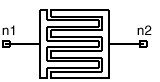
System Simulator > MS Interdigital Capacitor, Series (MSICAPSE)
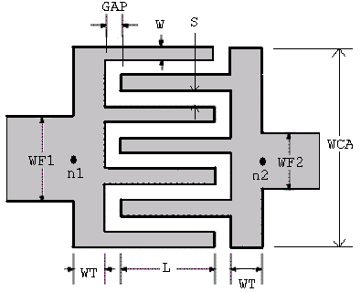
Notes1. The feeding lines widths, WF1 and WF2, must be less than (or equal to) the total width of the capacitor: WF1 £ WCA and WF2 £ WCA. 2. The finger width, W, and the spacing between adjacent fingers, S, are the same for all fingers. 3. The model takes into account the effect of the steps from the feeding lines to the terminal strips. 4. The capacitor width WCA is an optional parameter,
with a default value of (N*W+(N-1)*S). It can be set to a value larger
than the default value (see figure below). The user will get an error
message if WCA is set less than the default value. 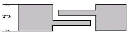 5. The terminal strip width WT can be set to zero. In this case, the user has to set WF1=WF2=WCA, and thus, the response will not include the effects of the terminal strips and the steps. The user has to add them using the appropriate TRL and STEP elements. 6. In the case of odd number of fingers, the model assumes that (N+1)/2 fingers are connected to port 1, while (N-1)/2 fingers are connected to port 2, as shown in the dimensional drawing. 7. The capacitance at the end of each finger and the small strips, of length GAP, at the beginning of each finger (outside the overlap region) are taken into account in the model. Netlist FormMSICAPSE:NAME n1 n2 N=val W=val S=val
L=val WT=val Netlist ExampleMSICAPSE:ICAPSE 1 2 N=25 W=40UM S=10UM L=76UM WT=50UM WF1=625UM WF2=625UM GAP=2UM SUB=SUB1 where sub1 needs to be defined in the corresponding .sub statement. References1. J. Hobdell, “Optimization of Interdigital Capacitors”, IEEE Trans. on MTT, Sep. 1979, pp. 788-791. 2. X. She, and Y. Chow, “Interdigital Microstrip Capacitor as a Four-Port Network”, IEE Proc., Pt. H, June 1986, pp. 191-197.
HFSS视频教程 ADS视频教程 CST视频教程 Ansoft Designer 中文教程 |
|
Copyright © 2006 - 2013 微波EDA网, All Rights Reserved 业务联系:mweda@163.com |
|


