|
 Ansoft Designer / Ansys Designer 在线帮助文档: Ansoft Designer / Ansys Designer 在线帮助文档:
System Simulator >
System Component Models >
WCDMA Multi-Antenna >
Multipath Rayleigh Fading Channel for Linear Antenna Array (MRFCHLAA)
Multipath Rayleigh Fading Channel for Linear
Antenna Array (MRFCHLAA)
Notes
1. This model can be used to simulate a Multipath
Rayleigh Fading Channel and then generate the signal at each antenna
when Linear Antenna Array is used in the receiver.
2. The Doppler power spectrum for Multipath Rayleigh
Fading Channel is given by [1][2]:
 (1) (1)
where b is the average received power, fm
= wm/2p is the maximum Doppler shift given by Vm/λ where Vm is mobile velocity
and l is the wavelength of the transmitted
signal at frequency fc.
3. Representing the RF channel as a time-variant
channel and using a base-band complex envelope representation,
the channel impulse response can be expressed as
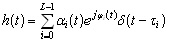  (2) (2)
where L is the number of paths, the amplitude ai(t)
for the ith path is Rayleigh distributed random variable,
the phase shift f(t) is uniformly
distributed, ti =>0 is the channel delay.
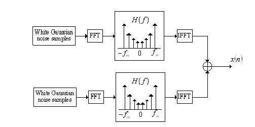
Since the Rayleigh fading process ai(t)ejfi(t) is complex,
the in-phase process and quadrature process for each path are implemented
separately, as shown in Fig.1.
Fig. 1 Block diagram of Rayleigh fading simulator
Based on Eqn.(2), both the in-phase process and the quadrature process
can be generated by passing a White Gaussian noise process through
a baseband filter which has the following frequency response:
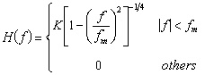 (3) (3)
where K is constant to normalize the frequency response. The
above frequency response is generated in the frequency domain using
FFT with length = 2048 points. Each point (0 <= K <=
length -1) corresponds to a certain frequency (fk) by
means of the following equation:
fk = k x fs (4)
where fs is the frequency sampling interval typically chosen
to be on the order of fm/10.
The above frequency response has an even real part and an odd imaginary
part to guarantee that the filtering process will generate a real in-phase
and quadrature correlated Gaussian processes. Each two generated
Gaussian processes are combined to generate a Rayleigh fading process.
It is important to point out that whether in-phase process or quadrature
process is correlated among different points but the two processes
are generated independently and therefore, uncorrelated.
Assume that channel delay for each path can be expressed by Di
samples. Each generated Rayleigh fading process corresponds to
a path with a user-specified delay Di and relative
power Pi, 0 <= i <= L-1. The expected
output along the ith fading path should be the input signal delayed
by Di samples and Rayleigh-faded with the specified
ith relative power Pi. The total average power
contribution from all paths is always normalized to unity. This is accomplished
by setting the standard deviation of the ith generated in-phase
and quadrature correlated Gaussian processes to
 (5) (5)
These time series of the generated fading process is further increased
in the time domain to match the sampling rate of the input signal. This
is accomplished by linearly interpolating the fading process (i.e.,
inserting fading points between each two originally generated fading
points).
4. The above does not consider linear antenna array.
A uniformly spaced linear antenna array with J elements[3][4]
is considered, as shown in Fig.2.
Fig. 2 Block diagram of Linear Antenna Array
Assuming a signal with wavelength λ arrives
at the linear antenna array from a direction, which is called direction
of arrival (DOA) qi, and taking
the first element in the array as phase reference, the relative phase
shift of the received signal at the nth element can be expressed as
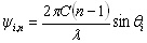 (6) (6)
where C is the array spacing. The vector channel impulse response
for the J elements can be expressed as
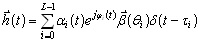  (7) (7)
where b(qi)
is the array response vector, which is given by
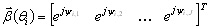 (8) (8)
where [ ]T denotes the matrix transpose.

5. Note that J samples are outputted successively
for each input sample.
Netlist Form
MRFCHLAA:NAME n1 n2 L=val J=val VM=val
C=val [SEED=val] D1=val P1=val A1=val
+ [D2=val . . . A12=val] [RIN=val] [ROUT=val]
Netlist Example
MRFCHLAA:1 1 2 L=2 J =2 VM = 12.0 C = 0.17 SEED
= 7359749 D1 = 0 P1 = 0 A1 = 0DEG +D2 = 150 P2 = 0 A2 = 10DEG
References
1. W. C. Jakes, Microwave Mobile Communications,
New York: Wiley, 1974.
2. T. S. Rappaport, Wireless Communications: Principles
and Practice, Prentice-Hall, 1996.
3. S. C. Swales, M. A. Beach, et al, “The
performance enhancement of multibeam adaptive base-station antennas
for cellular land mobile radio systems,”
IEEE Trans. Veh. Technol., vol. 39, pp. 56–67,
Feb. 1990.
4. S. Tanaka, A. Harada, et al, “Experiments on coherent adaptive antenna array diversity
for wideband DS-CDMA mobile radio,” IEEE Journal
on Selected Areas in Communications, vol. 18, No.8, pp.1495-1504,
Aug. 2000.


HFSS视频教程
ADS视频教程
CST视频教程
Ansoft Designer 中文教程
|
|