|
微波射频仿真设计 |
|
|
微波射频仿真设计 |
|
| 首页 >> Ansoft Designer >> Ansoft Designer在线帮助文档 |
|
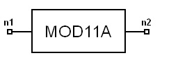
System Simulator > Modulator, 802.11a (MOD11A)
Limits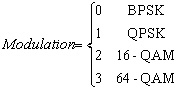
Notes1. This model can be used for modulation according to Gray-coded constellation mappings[1]. 2. The OFDM subcarriers can be modulated by using
BPSK, QPSK, 16-QAM, or 64-QAM modulation, depending on the RATE
requested. The encoded and interleaved binary serial input data shall
be divided into groups of NBPSC (1, 2, 4, or 6) bits and
converted into complex numbers representing BPSK, QPSK, 16-QAM,
or 64-QAM constellation points. The conversion shall be performed according
to Gray-coded constellation mappings[1]. The output values,
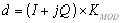
d, are formed by multiplying the resulting I + jQ value by a normalization
factor KMOD, as described in Eqn.(1).
Table I IEEE 802.11a Modulation-dependent normalization factor KMOD
Table II IEEE 802.11a BPSK encoding table
Table III IEEE 802.11a QPSK encoding table
Table IV IEEE 802.11a 16-QAM encoding table
Table V IEEE 802.11a 64-QAM encoding table
Netlist FormMOD11A:NAME n1 n2 [MODULATION =val] [RIN=val] [ROUT=val] Netlist ExampleMOD11A:1 1 2 MODULATION = 2 References1. IEEE Std 802.11a, Part 11: “Wireless LAN Medium Access Control (MAC) and Physical Layer (PHY) specifications: High-speed Physical Layer in the 5 GHz Band,” ISO/IEC 8802-11:1999/Amd 1:2000(E). 2. J. Terry and J. Heiskala, Proakis, OFDM Wireless LANs: A Theoretical and Practical Guide, Sams Publishing, 2002.
HFSS视频教程 ADS视频教程 CST视频教程 Ansoft Designer 中文教程 |
|||||||||||||||||||||||||||||||||||||||||||||||||||||||||||||||||||||||||||||||||||||||||||||||||||||||||||||||||||||||||||||||||||||||||||||
|
Copyright © 2006 - 2013 微波EDA网, All Rights Reserved 业务联系:mweda@163.com |
|
 (1)
(1)


