|
微波射频仿真设计 |
|
|
微波射频仿真设计 |
|
| 首页 >> Ansoft Designer >> Ansoft Designer在线帮助文档 |
|
System Simulator > Three Port Mixer (MIXER3P)
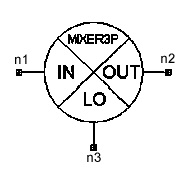
Notes1. Mixer S-parameters and noise parameters are treated as if they were measured on a two-port black box. The fact that the input and output frequencies are different is ignored during analysis. The input frequency is always used for interpreting any measurement data associated with this element. 2. Refer to <Install>\Examples\System\MixerDataFileExamples.adsn for three design examples using FLP and NMF MIXERSPURS data tables. 3. The nonlinear figures of merit (OIP2, OIP3, P1dB, and PSAT) are specified based on the reference LO power (PLO) parameter. 4. OIP3(dBm) = P1dB(dBm) + 10.64 dB. 5. Either OIP3 or P1dB can be specified, but not both. 6. If a MIXERSPURS data table is supplied, analysis will incorporate this table in a way similar to the 2-port mixer model. The main difference is that the LO frequency and power are determined from the signal driving the LO port (as opposed to being specified for the 2-port mixer model). The fundamental frequencies at the input (first) port and the LO (third) port will generate spurs at the output according to the supplied MIXERSPURS data table. 7. Note that the input and LO power levels may be optionally specified (see below) in MIXERSPURS data tables when performing frequency domain analysis. Specifying these power levels is required for discrete time analysis. The measured or simulated MIXERSPURS data is assumed to be applicable to the specified input LO and RF power levels. If during simulations, the signals driving the input and/or LO ports have power levels different from those specified in the supplied data table, the generated output spurs will be adjusted based on the actual power levels. The adjustment is typically reasonable for LO levels not exceeding the reference LO power by 3dBm and for RF levels not exceeding the reference RF power by 7dBm. 8. For frequency domain analysis, if a MIXERSPURS data table is referenced by the mixer, but the table includes no information on the reference LO and/or RF power levels, then the online reference LO power parameter PLO and the input tone with the maximum input power are used as the reference LO and RF powers respectively for the MIXERSPURS data table. 9. If no MIXERSPURS data is supplied, then the nonlinear and isolation figures of merit are used to compute the output signal. 10. An example of a MIXERSPURS data table (FLP format) is shown below: MIX_1 3-PORT ! This is the device name and number of ports * First Mixer Spur Table * Input signal level (dBm) LO level (dBm) MIXERSPURS MAXORDER = 10 PLO=10dBm PRF=-20dBm *0 1 2 3 4 5 6 7 8 9 10 20 18 32 40 50 60 70 80 90 100 110 30 0 40 50 60 70 80 90 100 110 40 20 50 60 70 80 90 70 110 50 30 60 70 80 70 80 110 60 40 70 70 80 90 100 70 50 80 90 100 110 80 60 90 100 110 90 70 100 100 100 80 110 110 100 120 11. For any MIXERSPURS data table: Netlist FormMixer3P:Name n1 n2 n3 [T=val] [MS11=val] .... Netlist Example
HFSS视频教程 ADS视频教程 CST视频教程 Ansoft Designer 中文教程 |
|
Copyright © 2006 - 2013 微波EDA网, All Rights Reserved 业务联系:mweda@163.com |
|


