|
微波射频仿真设计 |
|
|
微波射频仿真设计 |
|
| 首页 >> Ansoft Designer >> Ansoft Designer在线帮助文档 |
|
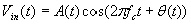
System Simulator > I-Q Demodulator (IQDEM)
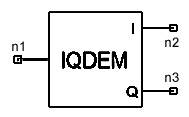
Notes1. For a given input signal Netlist FormIQDEM:Name n1 n2 n3 S=val P=val PHIQ=val [Rin=val] [Rout=val] Netlist ExampleIQDEM:1 1 2 3 S=1 P=0DEG PHIQ=0DEG
HFSS视频教程 ADS视频教程 CST视频教程 Ansoft Designer 中文教程 |
|||||||||||||||||||||||||||||||||||||||||||||||||||||||||
|
Copyright © 2006 - 2013 微波EDA网, All Rights Reserved 业务联系:mweda@163.com |
|