|
 Ansoft Designer / Ansys Designer 在线帮助文档: Ansoft Designer / Ansys Designer 在线帮助文档:
System Simulator >
System Component Models >
Modulators >
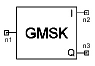
Gaussian Minimum Shift Keying Modulator (GMSK)
Gaussian Minimum Shift Keying Modulator
(GMSK)
Notes
1. This model modulates a sequence of input symbols
that have values in the range 0 to M – 1 , where M = 2NB.
The input to this model must be the symbol values Ai, where 0 £ Ai £ M 1,
and M = 2NB.
Each Ai input symbol value is then internally converted to the symbol
value Ki, where
Ki = 2 * (Ai + 1) – M. This implies that the values Ki may assume
are
– (M – 1), ...., –5, –3, –1, +1, +3, +5,
....., +(M – 1).
For example, when NB = 1 (i.e., each symbol is represented by one bit
as in the binary case), the values Ki may assume would be -1 and +1
only.
Each Ki symbol value (representing NB bits) is then upsampled by NUM_SAMPLES
by adding NUM_SAMPLES - 1 zeros after each Ki symbol value.
In other words, NUM_SAMPLES represents the number of samples
per symbol inside the GMSK modulator. Upsampling is performed because
this model involves a Gaussian filtering process to frequency
modulate the carrier.
The n-th sample of the in-phase and quadrature outputs of the GMSK modulator
is given by cos(theta(n)) and sin(theta(n)) respectively, where
theta(n) = 2 * PI * MODULATION_INDEX * SUM_1(Ki * q[n - i]) +
PI * MODULATION_INDEX * SUM_2(Ki)
where the limits of SUM_1 are from i = n - RESPONSE_LENGTH
+ 1 to n, and
the limits of SUM_2 are from i = 0 to n - RESPONSE_LENGTH.
The filter coefficients q[i], 0 £ i
£ RESPONSE_LENGTH * NUM_SAMPLES
- 1, are determined from integrating a Gaussian filter's impulse response
[1]. The duration of this impulse response (in samples) is RESPONSE_LENGTH
* NUM_SAMPLES.
The frequency response of the Gaussian filter is determined by the normalized
bandwidth (NORMALIZED_BW) which is given by B * T, where B is
the 3dB-bandwidth of the
Gaussian filter and T is the symbol duration. For example, the bit rate
in the GSM system
(NB = 1) is 3.69 mS, therefore, a normalized
bandwidth of NORMALIZED_BW = 0.3 (used by the GSM system) should
correspond to a Gaussian filter's 3dB-bandwidth of 81.25 KHz.
Netlist Form
GMSK:Name n1 n2 n3 NB=val MODULATION_INDEX=val
NUM_SAMPLES=val + RESPONSE_LENGTH=val NORMALIZED_BW=val
[Rin=Val] [Rout=Val]
Netlist Examples
1. Example 1:
GMSK:1 1 2 3 NB=1 MODULATION_INDEX=0.5 NUM_SAMPLES=2
+ RESPONSE_LENGTH=3 NORMALIZED_BW=0.3
The parameters in this example correspond to those
used by the GSM system. A typical input sequence and the corresponding
output sequence are shown in the following table:
2. Example 2:
GMSK 1 2 3 NB=2 MODULATION_INDEX=0.5 NUM_SAMPLES=3
+ RESPONSE_LENGTH=4 NORMALIZED_BW= 0.25
References
1. Raymond Steele, Mobile Radio Communications,
Pentech Press, 1992.


HFSS视频教程
ADS视频教程
CST视频教程
Ansoft Designer 中文教程
|
|