|
微波射频仿真设计 |
|
|
微波射频仿真设计 |
|
| 首页 >> Ansoft Designer >> Ansoft Designer在线帮助文档 |
|
System Simulator > Fixed-Point Accumulator (FXTACCUM)
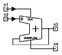
LimitsoutW > outD for signed arithmetic Notes1. This model is a fixed point accumumlator. It can be either clocked or non-clocked. If non-clocked, simply leave the clock signal port (the first input) open. When clocked, it is a rising edge triggered device. The trigger level is set to be 0.5 inside this model; therefore, care must be taken to make sure the input signal level is in accordance, a scaler may be needed to scale the incoming signal down in some cases. 2. The parameters outW, outD, ovf, quant, and arithtype are used to define the output format of the fixed point number. Note that, when the parameter useInAsOut is turned on, the previously mentioned parameters will be ignored; instead, the format of the output signal will be the same as the format of the input signal. That is to say, if one wants to use a different output format than the input format, he/she has to set useInAsOut to 0, and set the corresponding format. 3. The first output is the accumulated output signal, while the second output is the overflow output. When an overflow occurs during one accumulation step, a logic sigal “1” will be written to the second output to indicate an overflow. 4. The following plot shows the relationship between word length and precision.
Netlist FormFXTACCUM:NAME n1 n2 n3 n4 [useInAsOut=val] [outW=val] [outD=val] [ovf=val] [quant=val] [arithtype=val] [Rin1=val] [Rin2=val] [Rout1=val] [Rout2=val] Netlist ExampleFXTACCUM:1 1 2 3 4 outW=10 outD=10 ovf=0 quant=1 arithtype=1
HFSS视频教程 ADS视频教程 CST视频教程 Ansoft Designer 中文教程 |
||||||||||||||||||||||||||||||||||||||||||||||||||||||||||||||||||||||||||||||||||
|
Copyright © 2006 - 2013 微波EDA网, All Rights Reserved 业务联系:mweda@163.com |
|