|
微波射频仿真设计 |
|
|
微波射频仿真设计 |
|
| 首页 >> Ansoft Designer >> Ansoft Designer在线帮助文档 |
|
System Simulator > Frequency Multiplier (FMULT)
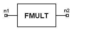
Notes1. This model produces an output spectrum according to the specified harmonic conversion gains (G1, G2, ..G9). For example, a single tone input power of 0dBm and G2 = -20dBm would result in a second harmonic output power of -20dBm. 2. This model supports conversion gain for harmonics beyond the 9th harmonic. This can be done by specifying GN, N > 9, in the netlist property of the FMULT component. 3. The specified conversion gains are based on a single tone reference power Pin. If multiple input tones are present at the input of the FMULT element, unwanted harmonics and intermodulation products will be generated. 4. For frequency domain analysis, specifying the parameter Pin is not necessary since the simulator will use the tone with the maximum input power as the reference input power. This will result in an ideal linear harmonic transformation for a single tone input. In other words, the conversion gain will be independent of the input power for a single tone input. This is not the case if more than one tone is present at the input. 5. For discrete-time domain analysis, it is necessary to accurately specify the reference input power Pin used for the specified conversion gains. For discrete-time analysis, the frequency multiplier is not independent of the input power for single or multitone inputs. 6. MINF and MAXF are used to block out unwanted
output harmonics for frequency domain analysis only. Netlist FormFMULT:Name n1 [n2] [N=val] [MS11=val] . . Netlist ExampleFMULT:1 1 2 N = 2 PIN = 0dBM G1 = -20 G2 = 20 G3 = -10 ...
HFSS视频教程 ADS视频教程 CST视频教程 Ansoft Designer 中文教程 |
|
Copyright © 2006 - 2013 微波EDA网, All Rights Reserved 业务联系:mweda@163.com |
|


