|
微波射频仿真设计 |
|
|
微波射频仿真设计 |
|
| 首页 >> Ansoft Designer >> Ansoft Designer在线帮助文档 |
|
System Simulator > Finite Impulse Response Filter (FIR)
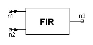
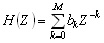
Notes1. This model implements FIR filter. The transfer function is of the form
2. The filter tap coefficients are provided in the data block in two-column XY DSP format. Each (X,Y) entry indicates the tap index and the corresponding tap coefficient (k, bk). 3. The second input is optional. If it is connected, this model operates as an edge triggered device, with the trigger level 0.5V.
Netlist FormFIR:NAME n1 n2 n3 FILE=”filename.dsp” [Rin1=val] [Rin2=val] + [Rout=val] [TRAN=val] Netlist ExampleFIR:1 1 2 3 FILE="firdata.dsp"
HFSS视频教程 ADS视频教程 CST视频教程 Ansoft Designer 中文教程 |
||||||||||||||||||||||||||||||||||||||||||||||||||||
|
Copyright © 2006 - 2013 微波EDA网, All Rights Reserved 业务联系:mweda@163.com |
|