|
微波射频仿真设计 |
|
|
微波射频仿真设计 |
|
| 首页 >> Ansoft Designer >> Ansoft Designer在线帮助文档 |
|
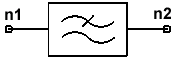
System Simulator > Elliptic Low Pass Filter (ELLPF_KP, ELLPF_FS, ELLPF_N)
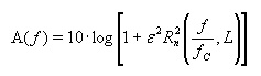
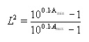
Notes1. The model ELLPF has been separated into three components: ELLPF_KP, ELLPF_N, and ELLPF_FS. The parameters KP, N and FS may not be used concurrently, and are required for the corresponding components. 2. The elliptic filter is equiripple in the pass band and the stop band (it has equal loss maxima in the pass band and equal loss minima in the stop band). The elliptic filter is used when a sharp transition region is desired for the lowest possible order (which defines the number of reactive elements needed for the filter implementation). 3. The model is described by the following1:
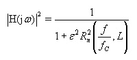
4. The magnitude of the transfer function, |H(jw)| is equal to the inverse of the loss:
5. There are three input options: 6. The normalized low pass prototype filter is designed for wc=1 (where wc=2pfc). A frequency transformation is performed for the low pass filter, where the transformed w is given by:
7. Range for N: 2 < N < 15 Netlist FormELLPF:NAME n1 n2 AMAX=val AMIN=val {FC=val,FS=val | FC=val,KP=val | FC=val,N=val}[R1=val] [R2=val] [IL=val] Netlist ExampleELLPF:1 1 2 FC=2ghz FS=2.1ghz AMAX=0.01 AMIN=40 ELLPF:2 1 2 FC=2GHZ N=10 AMAX=0.01 AMIN=40 ELLPF:3 1 2 FC=2GHZ kp=0.96 AMAX=0.01 AMIN=40 References1. Approximate Methods for Electronic Filter Design, Richard W. Daniels, Bell Telephone Laboratories, Inc., McGraw-Hill Book Company, 1974. 2. Handbook of Filter Synthesis, Anatol I. Zverev, John Wiley & Sons, 1967.
HFSS视频教程 ADS视频教程 CST视频教程 Ansoft Designer 中文教程 |
|
Copyright © 2006 - 2013 微波EDA网, All Rights Reserved 业务联系:mweda@163.com |
|