|
微波射频仿真设计 |
|
|
微波射频仿真设计 |
|
| 首页 >> Ansoft Designer >> Ansoft Designer在线帮助文档 |
|
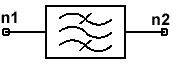
System Simulator > Elliptic Band Reject Filter (ELBRF_KP, ELBRF_FS, ELBRF_N)
Notes1. The model ELBRF has been separated into three components: ELBRF_KP, ELBRF_N, and ELBRF_FS. The parameters FL & FH, KP, and N may not be used concurrently. 2. The elliptic filter is equiripple in the pass band and the stop band (it has equal loss maxima in the pass band and equal loss minima in the stop band). The elliptic filter is used when a sharp transition region is desired for the lowest possible order (which defines the number of reactive elements needed for the filter implementation). 3. In the case ELBRF_KP, KP is a required parameter. 4. In the case ELBRF_N, N is a required parameter. 5. In the case ELBRF_FS, either FL or FH must be
provided as inputs. If only FL or FH is given, then the corresponding
values for FH and FL are calculated such that a geometrically symmetrical
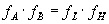
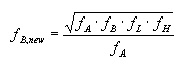
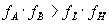
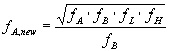
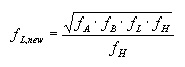
filter is defined: 6. If both FL and FH are defined such that the filter
is not geometrically symmetrical, then1,2: 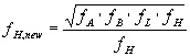 .
7. The normalized low pass model poles are then calculated for fc=1, and fS=(fH-fL)/(fB-fA) (where fc is the pass band cutoff frequency, and fs is the stopband edge frequency - see low pass elliptical filter model description). 8. The band reject model is described by the following1,2:
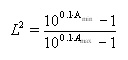
9. The magnitude of the transfer function, |H(jw)| is equal to the inverse of the loss:
10. Range for N: 2 < N < 15 Netlist FormELBRF:NAME n1 n2 AMAX=val AMIN=val {FA=val FB=val [FL=val|FH=val] | FA=val FB=val KP=val | FA=val FB=val N=val} Netlist ExampleELBRF:1 1 2 FA=2ghz FB=4GHZ FL=2.02GHz FH=3.96GHZ AMAX=0.01 AMIN=40 ELBRF:2 1 2 FA=2GHZ FB=4GHZ N=12 AMAX=0.01 AMIN=40 ELBRF:3 1 2 FA=2GHZ FB=4GHZ KP=0.99 AMAX=0.01 AMIN=40 References1. Approximate Methods for Electronic Filter Design, Richard W. Daniels, Bell Telephone Laboratories, Inc., McGraw-Hill Book Company, 1974. 2. Handbook of Filter Synthesis, Anatol I. Zverev, John Wiley & Sons, 1967.
HFSS视频教程 ADS视频教程 CST视频教程 Ansoft Designer 中文教程 |
|
Copyright © 2006 - 2013 微波EDA网, All Rights Reserved 业务联系:mweda@163.com |
|
 :
:
 :
:
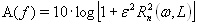 , where A(f) is
the loss in dB, and Rn is the nth order Tschebycheff
rational function,
, where A(f) is
the loss in dB, and Rn is the nth order Tschebycheff
rational function,  , and
, and