|
微波射频仿真设计 |
|
|
微波射频仿真设计 |
|
| 首页 >> Ansoft Designer >> Ansoft Designer在线帮助文档 |
|
System Simulator > Edge Modulator (EDGEMOD)
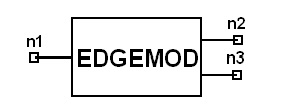
Notes1. This model converts each three input bits into
a pair of in-phase and quadrature output signals based on the EDGE 8PSK
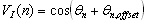
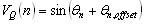
modulation. The in-phase and quadrature output values at time index
n are calculated using equations FormEDGEMOD:Name n1 n2 n3 [Rin=val], [Rout1=val], [Rout2=val] ExampleEDGEMOD:1 1 2 3 References1. GSM 05.04 (i.e., ETSI EN 300 959): “Digital cellular telecommuneications system (Phase 2+); Modulation”
HFSS视频教程 ADS视频教程 CST视频教程 Ansoft Designer 中文教程 |
||||||||||||||||||||||||||||||||||||||||||
|
Copyright © 2006 - 2013 微波EDA网, All Rights Reserved 业务联系:mweda@163.com |
|
 ,
, ,
, ,
, ,
, ,
, ,
, ,
, .
.


