|
微波射频仿真设计 |
|
|
微波射频仿真设计 |
|
| 首页 >> Ansoft Designer >> Ansoft Designer在线帮助文档 |
|
System Simulator > PI/4 DQPSK Modulator (DQPSKMOD)
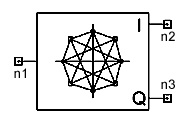
Notes1. This model performs PI/4DQPSK modulation. The
input to this model is assumed to be the symbol values A(n) = 0, 1,
2, 3 for n ³ 0. The modulation information
is stored differentially in the phase. Specifically, the in-phase and
quadrature outputs of the modulator are given by cos(theta(n)) and sin(theta(n))
respectively, where Netlist FormDQPSKMOD:Name n1 n2 n3 [Rin=Val] [Rout=Val] Netlist ExampleDQPSKMOD:1 1 2 3
HFSS视频教程 ADS视频教程 CST视频教程 Ansoft Designer 中文教程 |
||||||||||||||||||||||||||||||||||||||||||
|
Copyright © 2006 - 2013 微波EDA网, All Rights Reserved 业务联系:mweda@163.com |
|


