|
 Ansoft Designer / Ansys Designer 在线帮助文档: Ansoft Designer / Ansys Designer 在线帮助文档:
System Simulator >
System Component Models >
Demodulators >
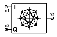
PI/4DQPSK Demodulator (DQPSKDEM)
PI/4DQPSK Demodulator (DQPSKDEM)
Notes
1. This model performs PI/4DQPSK demodulation.
The in-phase and quadrature inputs to this model (ri(n) and rq(n), n
³ 0) are assumed to have been modulated
by the model PI/4DQPSK.
Since the input to the modulator PI/4DQPSK is assumed to be the symbol
values A(n) = 0, 1, 2, 3, n ³ 0,
the recovered symbol values at the output of the demodulator B(n) are
also 0, 1, 2, 3, for n ³ 0.
Let the received complex (in-phase + quadrature) symbols be r(n) = ri(n)
+ j rq(n), n ³ 0. The demodulation
process is performed as follows for n ³
0:
B(n) = 0, Re{r(n)r*(n-1)} > 0, Im{r(n)r*(n-1)}
> 0
B(n) = 1, Re{r(n)r*(n-1)} < 0, Im{r(n)r*(n-1)}
> 0
B(n) = 2, Re{r(n)r*(n-1)} > 0, Im{r(n)r*(n-1)}
< 0
B(n) = 3, Re{r(n)r*(n-1)} < 0, Im{r(n)r*(n-1)}
< 0
where r*(n-1) is the complex conjugate of r(n-1), and Re{.} and Im{.}
denote the real and imaginary operators respectively. The following
initial condition is always assumed:
r(-1) = cos(PI/4) + j sin(PI/4)
Netlist Form
DQPSKDEM:Name n1 n2 n3 [Rin1=Val] [Rin2=Val]
[Rout=Val]
Netlist Example
DQPSKDEM:1 1 2 3


HFSS视频教程
ADS视频教程
CST视频教程
Ansoft Designer 中文教程
|
|