|
微波射频仿真设计 |
|
|
微波射频仿真设计 |
|
| 首页 >> Ansoft Designer >> Ansoft Designer在线帮助文档 |
|
System Simulator > Depuncturer (DPUNC)
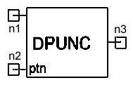
Notes1. This model can be used to perform the inverse procedure of “Puncturing”. Depuncturing is done by simply inserting dummy bits into the locations that were punctured at the output of convolutional encoder. The value of dummy bits is set to “zero” in this model. Please refer to the Puncturer model for details. Netlist FormDPUNC:NAME n1 n2 n3 N=val [RIN1=val] [RIN2=val] [ROUT=val] Netlist ExampleDPUNC:1 1 2 3 N=6 References1. J. G. Proakis, Digital Communications, McGraw-Hill, 2001.
HFSS视频教程 ADS视频教程 CST视频教程 Ansoft Designer 中文教程 |
|||||||||||||||||||||||||||||||||||||||||||||||
|
Copyright © 2006 - 2013 微波EDA网, All Rights Reserved 业务联系:mweda@163.com |
|


