|
微波射频仿真设计 |
|
|
微波射频仿真设计 |
|
| 首页 >> Ansoft Designer >> Ansoft Designer在线帮助文档 |
|
System Simulator > Delay Modulation (Miller Coding) Model (DLYMOD)
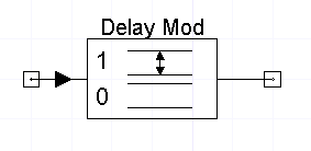
NotesFor Delay modulation (Miller Coding), a high input value is represented by a transition at the midpoint of the bit interval. A low input value maintains the state value, unless two low input values occur in a row. When this happens, a transition occurs at the end of the bit interval.
Netlist FormADLYMOD:NAME n1 n2 Nexsys_component=dly_mod Level=val N=val [RIN=val] [ROUT=val] Netlist ExampleADLYMOD:1 1 2 Nexsys_component=dly_mod Level=2.2 N=2 Reference[1] Bernard Sklar, Digital Communications Fundamental and Applications, Prentice-Hall 1988
HFSS视频教程 ADS视频教程 CST视频教程 Ansoft Designer 中文教程 |
||||||||||||||||||||||||||||||||||||||||||||||||||||||||||||||||||||||||||||||||||||||||||||||||||||||||||||||
|
Copyright © 2006 - 2013 微波EDA网, All Rights Reserved 业务联系:mweda@163.com |
|


