|
微波射频仿真设计 |
|
|
微波射频仿真设计 |
|
| 首页 >> Ansoft Designer >> Ansoft Designer在线帮助文档 |
|
System Simulator > Dicode RZ Formatting Model (DICRZ)
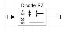
NotesFor Dicode RZ, a change in input state (0->1 or 1->0) will produce a half bit wide pulse of opposite polarity from the prior pulse transmitted. A half bit wide zero is transmitted to fill the bit wide time interval. For no state change at the input (0->0 or 1->1), a bit wide zero voltage is transmitted. Initial reference pulse is equal (-level) with 0 previous input.
Netlist FormADIC_RZ:NAME n1 n2 Nexsys_component=dic_rz Level=val N=val [RIN=val] [ROUT=val] Netlist ExampleADIC_RZ:1 1 2 Nexsys_component=dic_rz Level=2.2 N=2 Reference[1] Bernard Sklar, Digital Communications Fundamental and Applications, Prentice-Hall 1988
HFSS视频教程 ADS视频教程 CST视频教程 Ansoft Designer 中文教程 |
||||||||||||||||||||||||||||||||||||||||||||||||||||||||||||||||||||||||||||||||||||||||||||||||||||||||||||||
|
Copyright © 2006 - 2013 微波EDA网, All Rights Reserved 业务联系:mweda@163.com |
|


