|
微波射频仿真设计 |
|
|
微波射频仿真设计 |
|
| 首页 >> Ansoft Designer >> Ansoft Designer在线帮助文档 |
|
System Simulator > Complex to Real Converter (CTOR)
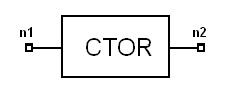
NotesThis model converts the complex input signal Vin(t) into a real output signal Vout(t) accroding to the following equation: For PHASE = 0deg, the output will equal the real part of the input signal, and for PHASE = 90 deg the output will equal the imaginary part of the input signal . Netlist FormCTOR:Name n1 n2 PHASE=val [Rin1=val] [Rin2=val][Rout=val] Netlist ExampleCTOR:1 1 2 PHASE=90DEG
HFSS视频教程 ADS视频教程 CST视频教程 Ansoft Designer 中文教程 |
|||||||||||||||||||||||||||||||||||||
|
Copyright © 2006 - 2013 微波EDA网, All Rights Reserved 业务联系:mweda@163.com |
|


