|
微波射频仿真设计 |
|
|
微波射频仿真设计 |
|
| 首页 >> Ansoft Designer >> Ansoft Designer在线帮助文档 |
|
System Simulator > Crystal, ESR, Parallel Resonance (CRYRP)
Notes1. ESR is the equivalent series resistance for the crystal. 2. L is the crystal’s nominal inductance and can be calculated from nominal capacitance C and series-resonance frequency FS. 3. F1 and F2 specify the frequency range for crystal device. The nominal capacitance and Q of the crystal will fall in the manufacture specified value in this frequency range. 4. TC is defined in PPM (parts per million).
For example, a crystal has nominal value of FS at 298 K. At temperature
TEMP, the resulting value of the series-self resonance frequency,
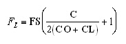
Fs, is calculated as 5. MODE is used to specify the crystal’s overtone mode and must be an odd positive integer. Setting MODE to a value greater than 1 results in series self-resonances at FS and at FS/MODE. For example, setting FS equal to 222MHz and MODE equal to 5 results in series resonances at 222 MHz (the fifth-overtone resonance) and 222/5 MHz, or 44.4 MHz (the fundamental resonance). 6. The load capacitance, CL, is an external capacitance that sets a point on the reactance curve at which the crystal will resonate. CL comprises a combination of the circuit’s discrete load capacitance, stray board capacitance, and capacitance from the operation of the Miller effect in active devices. When an oscillator presents some amount of load capacitance to a crystal, the crystal is said to be parallel-resonant, and a value of load capacitance, CL, must be specified. If the circuit does not exhibit capacitive loading, the crystal is said to be series-resonant, and no value of load capacitance is specified. A quartz crystal’s parallel-resonance operating frequency is based on:
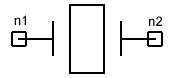
where FS is the series-resonance frequency, FL is the parallel-resonance frequency, CL is the crystal load capacitance, CO is the crystal shunt capacitance, and C is the crystal nominal capacitance. Netlist FormCRYRP:Name n1 [n2] C=val FS=val [ESR=val]
[CO=val] [CL=val] [TC=val] Netlist ExampleCRYRP:1 1 2 C=0.3ff ESR=42 FS=273.75MHz MODE=3 TC=50 TEMP=300
HFSS视频教程 ADS视频教程 CST视频教程 Ansoft Designer 中文教程 |
|
Copyright © 2006 - 2013 微波EDA网, All Rights Reserved 业务联系:mweda@163.com |
|