|
微波射频仿真设计 |
|
|
微波射频仿真设计 |
|
| 首页 >> Ansoft Designer >> Ansoft Designer在线帮助文档 |
|
System Simulator > Multiplexer with Eight Inputs, Complex (CMUX8)
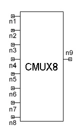
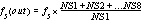
NotesThis model is used to multiplex N (1£ N £ 8) complex input signals with same sampling rate into a single complex output signal. Note that if only N input ports are used to do the multiplexing, the remaining ports are not used. If TYPE is set to 0, then the sampling rate of the output signals will not change. Otherwise, the sampling rate of the output port can be calculated
as If the incoming signal is real, the simulator will automatically insert a real-to-complex converter internally. Netlist FormCMUX8:Name n1 n2 n3 n4 n5 n6 n7 n8 n9 [TYPE=val] [N=val] [NS1=val] [NS2=val] [NS3=val] [NS4=val] [NS5=val] [NS6=val] [NS7=val] [NS8=val] [Rin1=val][Rin2=val] [Rin3=val] [Rin4=val] [Rin5=val] [Rin6=val] [Rin7=val] [Rin8=val] [Rout=val] Netlist ExampleCMUX8:1 1 2 3 4 5 6 7 8 9 TYPE=0 N=5 NS1=1 NS2=1
NS3=1 NS4=0 NS5=1 NS6=0 NS7=0 NS8=0
HFSS视频教程 ADS视频教程 CST视频教程 Ansoft Designer 中文教程 |
||||||||||||||||||||||||||||||||||||||||||||||||||||||||||||||||||||||||||||||||||||||||||||||||||||||||||||||||||||||||||||||||||||||||||||||||||||||||
|
Copyright © 2006 - 2013 微波EDA网, All Rights Reserved 业务联系:mweda@163.com |
|