|
微波射频仿真设计 |
|
|
微波射频仿真设计 |
|
| 首页 >> Ansoft Designer >> Ansoft Designer在线帮助文档 |
|
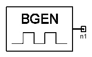
System Simulator > Periodic Binary Bit Generator (BGEN)
 o
NotesThis model generates a periodic binary sequence of T's and F's with a BR bit rate . The period of this bit sequence is given by PERIOD and the bits generated during each period are specified by BIT_PATTERN in binary format. For example, if BIT_PATTERN is set to 1010 and PERIOD is set to 4, then output sequence will be FTFTFTFT..... Note that the pattern always starts with the least significant bit of BIT_PATTERN. It is common that the parameters T and F are set to the default values of 1 and 0 respectively. In this case, this model outputs a binary sequence. Netlist FormBGEN:Name n1 NB=val BIT_PATTERN=val
PERIOD=val BR=val Netlist ExampleBGEN:1 1 NB=200 BIT_PATTERN=10 PERIOD=4 BR=2KHZ
HFSS视频教程 ADS视频教程 CST视频教程 Ansoft Designer 中文教程 |
||||||||||||||||||||||||||||||||||||||||||||||||||||
|
Copyright © 2006 - 2013 微波EDA网, All Rights Reserved 业务联系:mweda@163.com |
|


