|
微波射频仿真设计 |
|
|
微波射频仿真设计 |
|
| 首页 >> Ansoft Designer >> Ansoft Designer在线帮助文档 |
|
System Simulator > Bit Error Rate Probe (BERP)
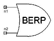
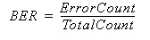
Notes1. This model is used to calculate the BER in a digital communications systems by comparing a transmitted stream of binary bits (Input1) with the corresponding received data stream (Input2). The total error count (ErrorCount) is incremented by 1 each time a mismatch is detected between the two input streams. The final BER value is computed as:
Systems with low BERs require an increased number of bits to be transmitted through the system to obtain an accurate measure of BER Netlist FormBERP:Name n1 n2 [Initsamp1=val] [Initsamp2=val] [Rin1=val] [Rin2=val] Netlist ExampleBERP:My_Berp 1 2
HFSS视频教程 ADS视频教程 CST视频教程 Ansoft Designer 中文教程 |
|||||||||||||||||||||||||||||||||||||||||||||||
|
Copyright © 2006 - 2013 微波EDA网, All Rights Reserved 业务联系:mweda@163.com |
|