|
|
|
|
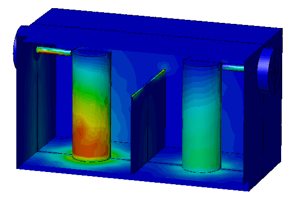
Surface power loss distribution
|
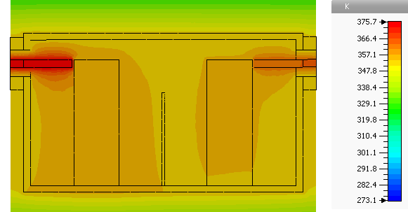
Temperature distribution
|
|
|
|
|
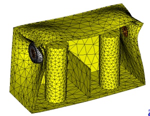
Mechanical deformation |
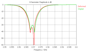
Shifted S-Parameters |
This example demonstrates how to perform a parameterized coupled simulation of a narrow band filter, containing two coaxial resonators. The whole simulation workflow involves the coupling of four linked CST-simulation tasks. Due to ohmic and surface losses, the structure is heated. This heating leads to a mechanical deformation, which de-tunes the filter. The final simulation uses the deformation information to compute the shifted S-parameter curves for the heated and deformed structure.
To create the filters housing a shelled brick was created. Afterwards the coaxial connectors were added by defining and mirroring various cylinders. The interior of the filter contains an aperture, created with the brick tool and two cylinders. The regions where fields are most concentrated is where the coaxial feeds are pointing at the resonators cylinders. To obtain accurate results two mesh refinements were defined for the coaxial feeds. The height of the aperture is parameterized and later used for a parameter sweep.
The project consists of a master project, which is visible after opening in CST STUDIO SUITE and four simulation tasks, which are basically derived sub projects. To access these simulation tasks one has to switch to the schematic view of the master project:
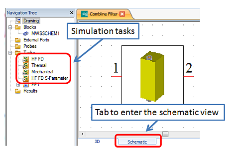
All four simulation tasks were derived from the master project and contain further problem-specific settings which are described below:
The first project is a tetrahedral grid based simulation with the frequency domain solver. Three monitors were defined to record electric-, magnetic- and loss-fields. After the solver process has been finished the thermal surface- and volume-loss distributions are prepared for the thermal simulation by a template.
This project uses the thermal loss distributions calculated by the HF FD task to compute a temperature distribution on a hexahedral grid. Besides the loss distributions, convection boundaries were defined on the outer walls of the filters housing.
In combination with a reference temperature, this project uses the temperature distribution from the previous one to compute the thermal expansion of the filter. Therefore the coaxial waveguide ports must be fixed mechanically with displacement boundary conditions.
Finally the mechanical displacement information is used with the sensitivity analysis to compute the S-parameters of the deformed structure. This project is tetrahedral based, since the sensitivity analysis operates only on tetrahedral based grids. The displacement information was imported with the field import source and then linked to the sensitivity analysis.
During the workflow a couple of interesting results appear:
thermal loss distributions on surfaces and inside volumes
temperature distribution
mechanical deformation
S-parameter curves for the original and the deformed structure
Especially the S-parameter curves of the deformed structure play an important role for filter designers. Actually this filter was not designed very well, since the influence of temperature changes affects the electrical filter behavior too much.
The example also contains three tables with S-Parameter result curves vs. the height of the aperture:
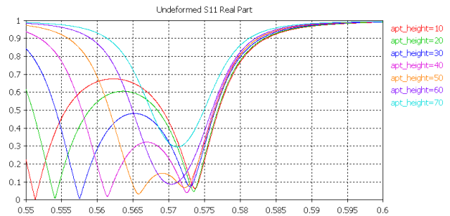
This demonstrates that one can easily perform a parameter sweep or an optimization process with the parameterized sequence of simulation tasks.