CST MICROSTRIPES can be used to find the scattering parameters of a multi-port device and express them in a number of ways, namely:
• S-matrix
• Return and transmission in dB
• Y-matrix and Z-matrix
• S-matrix ‘normalized’ to a given impedance
• VSWR for each port
• Input impedance for each port: i.e. the wave impedance for TE ports and the terminal impedance for TEM ports.
In addition, for the waveguide or transmission line constituting each port, CST MICROSTRIPES gives the:
• Propagation constant (except for ‘wire-ports’)
• Impedance: i.e. the travelling wave impedance for TE ports and the characteristic impedance for TEM ports.
All these parameters are given as a function of frequency. The propagation constants may be used to move the port reference planes without repeating the simulation.
For 2-port devices (only), CST MICROSTRIPES can reduce the number of simulations to 1 by exploiting either:
• Symmetry with respect to ports (the device is unchanged by exchanging the ports).
• Losslessness (the device is unchanged by reversing the flow of time).
In these circumstance it is possible to perform a single simulation (exciting either port), and then infer the results of a second simulation by port-exchange or time-reversal.
To take advantage of this capability, it is firstly necessary to set one of the two ports to not-excited in Build. Secondly, either ‘Symmetric w.r.t. ports’ and/or ‘Lossless’ must be selected in the 2-port CST MICROSTRIPES settings. Unless the excitation is turned off for one of the ports, CST MICROSTRIPES will ignore these settings and perform two simulations, exciting each port in turn.
The ‘Identical Ports’ ports option should be selected if both ports consist of the same type of waveguide or transmission line - this allows CST MICROSTRIPES to achieve better accuracy with the ‘Lossless’ option. If ‘Symmetric w.r.t. to Ports’ is chosen then the ports are considered identical.
Note that for a device to be symmetric w.r.t. ports, the port reference planes must be an equal distance from the mid-point of the device.
By default, CST MICROSTRIPES finds the scattering parameters of a N-port device by performing N (linearly independent) simulations, exciting each port in turn. It is then necessary to analyse the time domain data from each simulation using the Resolve Waves module.
This resolves the electromagnetic fields in each port of the device into in-going and out-going (incident and scattered) waves as a function of frequency. These N sets of frequency domain scattering data form the input for the S-Matrix (N-Port) module.
Having taken the 3D-TLM Simulator output for the first simulation, and calculated the amplitude and phase of the in-going and out-going waves (using Resolve Waves), it is found that there is a wave of small amplitude entering the output ports (non-excited ports) at most frequencies. This wave entering the device is due to the reflection from the terminations, which have a fixed impedance and only match the wave impedance at a single frequency (except for transmission lines carrying a TEM wave where the wave impedance is constant).
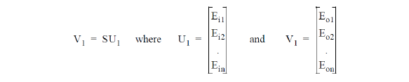
From the first simulation we have
and where Ein and Eon are the in-going and out-going signals on the nth port, and S is the scattering matrix.
Now the process is repeated; the simulation, and the determination of input/output conditions, but this time with the device excited on a different port. This yields a second set of input and output conditions U2 and V2 which are linearly independent from the first set and which also satisfy V2 = SU2. Repeating the process until a simulation has been performed with the excitation on each of the ports of the device, gives sufficient information to determine the complete scattering matrix. Thus

so

If the waveguides forming the various ports are of different types, then a given power flow may correspond to different wave amplitudes in each port. In this case (assuming reciprocity) the scattering matrix may be normalized simply by replacing each of the elements Sij and Sji by their geometric mean (taking care to preserve their phase).
By default, scattering parameters are calculated both as complex numbers and in dB. Provided the dB option is not deactivated by the user, then in addition to ‘return’ and ‘transmission’ in dB, CST MICROSTRIPES will also give the ‘loss’ defined as

in dB. This is simply the fraction of the power entering port i which never re-emerges out of any port.
The Stripes to Touchstone translator allows a device whose scattering matrix has been found using CST MICROSTRIPES to be incorporated into TouchStone circuits.
Apart from the difference in file formats between CST MICROSTRIPES and TouchStone, the two programs use two different types of S-matrix. The TouchStone S-matrix is drawn from the circuit theory tradition where electrical devices are commonly connected with cables of a standard characteristic impedance (typically 600W or 50W). If a device presents an impedance between a pair of terminals which differs from this standard, then the reflection that occurs at the terminals when the standard impedance cable is connected, is counted as part of the S-matrix of the device.
The CST MICROSTRIPES S-matrix is drawn from the microwave or waveguide tradition where a guide cannot be wholly characterized by a single impedance value. If one type of guide connects to a different type at a port of a device, then the reflection at the port will depend on the details of the two waveguide geometries, and generally cannot be determined easily (except by using CST MICROSTRIPES). Because of this, this type of S-matrix is defined with matched ports, that is excluding any reflection at the ports.
There is a second difference between the two types of S-matrix; the circuit theory matrix relates incident and reflected voltages measured across the terminals. With single conductor waveguides there is no general agreement about where the voltage is to be measured, and so the CST MICROSTRIPES S-matrix relates the square roots of the incident and reflected power flows (which may be considered to represent some undefined voltages). In this scheme, the S-matrix of a reciprocal device is always symmetric, and an element Sij of magnitude 0.707 always represents a coupling of -3dB. This is true even when the ports are in different types of line, as for example in a coax to rectangular guide transition.
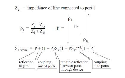
The translator thus performs three tasks; converting to absolute voltages, adding reflections at ports, and changing file formats. To do this the translator needs to know both the actual characteristic impedance of the lines forming each port of the device and the impedance of the lines to which they are to connect. The calculation performed is; conversion to absolute voltages...
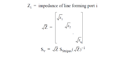
and addition of reflection at ports...
There is a small but significant class of electromagnetic problems which are fundamentally two dimensional apart from a sinusoidal variation of the field in the third dimension. In particular there are problems where a rectangular wave guide of constant width varies in height or bends or branches in the E-plane only. In such cases enormous saving in computational resources may be made by solving the two dimensional problem numerically, and accounting for the sinusoidal variation in the third dimension analytically.
Note that the corresponding type of problem where rectangular waveguide of constant height varies in width or bends or branches in the H-plane only, may be reduced to two dimensions immediately and without any consideration of the third dimension. This is because in this case the field is unvarying in the third dimension. The two types of problems are not dual because the same (not dual) boundary conditions apply in both cases. That is, in both cases the boundaries in the third dimension are conducting, since magnetic walls are not commercially available.
A two dimensional model of the device with E-plane symmetry is prepared for simulation. The external boundary conditions for the symmetry faces of the model should be set to ‘magnetic wall’. Scatter parameters for the TEM wave excited in the two dimensional model are obtained, and then mapped into the required three dimensional results. The cutoff frequency of the mode corresponding to the sinusoidal variation across the waveguide must be set in the CST MICROSTRIPES Settings dialog.