 Block
Block
All primitives dialogs have certain features in common. At the bottom, they have a Create and a Close button used to create the solid with the given parameters and to close down the dialog.
At the top of the Input parameters area are two items, Name and color. You do not need to change either of these since default values are provided. If the name specified has already been assigned to another entity, then Build ensures that the assigned name is unique by appending "_n" to the name (where n is an integer).
The user may change the color of the object by pressing the colored rectangle and selecting a color from the color window. The color of an object may later be redefined using the Rename/Re-color function.
In general, solids can only be created aligned to the x, y, or z axes. This will be suitable for the majority of models. If it is not, then entities can be rotated after creation using the Transform function.
On windows such as Elliptic Cylinder, there is a box to select the direction (default +z) and edit boxes for the major and minor radii (default X and Y radius). If the direction is changed then the radius labels alter accordingly.
It is recommended that variables are used to define key aspects of the geometry, such as size of a patch antenna, or location of a port. These variables can then be easily edited, or defined using a range of values allowing multiple models to be analysed in one go. This can lead to rapid identification of the best solution. The use of variables also allows easy association of parts, by using the same variable name for multiple objects.
Expressions can also be used to define the geometry, for example the position of a patch can be defined as 6.5+thickness.
In many instances a zero can be used to define the length of a primitive in order to obtain a thin face.
To save typing, and to enable the user to correctly position input points, many dialogs have a Pick point button next to three text input areas for entering a point's coordinates. The user may press the Pick point button then click on any vertex in the viewing area with the left mouse button. If the pick is successful, the coordinates of the vertex will be entered automatically into the text fields; otherwise, a beep will indicate failure.
When creating rotationally symmetric solids, the input requires a point on the axis, so it is useful to obtain the coordinates of the center of a circle. Therefore, if the mouse click is not on a vertex but on a circular (or elliptic) edge, it's center will be returned.
Two modifiers can be used with the Pick point facility to obtain positions at which there is no vertex. The <Shift> key enables the user to pick any screen position in the viewing plane. This modifier is only useful in one of the orthogonal views such that the viewing plane is known. For example, if the view is such that the y and z axes are in the plane of the screen, then any position picked will be in the plane x = 0. The other modifier is the <Ctrl> key, which is used to pick positions on existing edges or faces.
<Shift> and <Ctrl> used simultaneously will return the mid point of an edge or the center of a face.
In dialogs containing three text fields for the input of a vector, there will usually be a button Pick vector. When this is pressed the user should pick two vertices from the viewing area to define the vector. The vector is created from the first pick to the second. The user may pick away from any vertices for either pick to signify the origin.
Picking of vertices without modifiers will only be successful when the display mode includes edges, not when only shaded faces are displayed. Conversely, for sweeping operations where a face needs to be picked, this can only be done when the display includes shaded faces.
Block
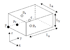
• corner: p
• center: c
• X base center: px
• Y base center: py
• Z base center: pz
• Lengths: Lx, Ly, Lz
 Sphere
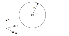
• center point: c
• Radius: r
 Torus
Torus
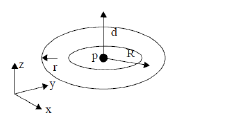
• center point: p
• Axis direction: d
• Major radius: R
• Minor radius: r
 Helix
Helix
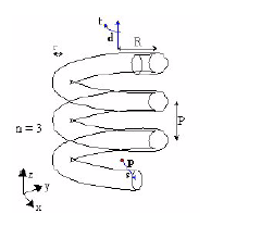
• Base point: p
• Axis direction: d
• Start direction: s
• Major radius: R
• Minor radius: r
• Pitch length: P
• Number of cycles: n
• Right/left handed: t
 Pyramid

• Base point: p
• Axis direction: d
• x base length: b1
• y base length: b2
• x top length: t1
• y top length: t2
• Height: h
The base lengths must both be positive while either of the top lengths may be zero.
 Prism
Prism
A set of points is used to define a planar structure, which is then extruded in the third dimension.
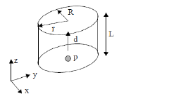
 Cylinder

• Axis point: p
• Axis direction: d
• Length: L
• Radius: r
 Elliptic Cylinder
• Axis point: p
• Axis direction: d
• Length: L
• X radius: R
• Y radius: r
 Cone
Cone
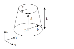
• Base point: p
• Axis direction: d
• Length: L
• Base radius: b
• Top radius: t
•
 Elliptic Cone
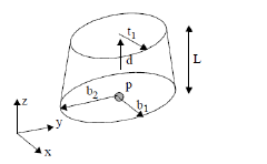
• Base point: p
• Axis direction: d
• Length: L
• Base X radius: b1
• Base Y radius: b2
• Top X radius: t1
The top Y radius is calculated so that the top radii are in the same ratio as the base.
 Le
Le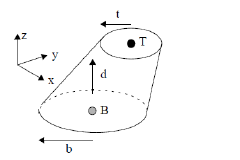 aning Cone
• Base center point: B
• Base radius: b
• Top center point: T
• Top radius: t
• Normal: d
 Rectangular Tube
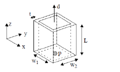
• Base center point: p
• Direction: d
• Inner X width: w1
• Inner Y width: w2
• Length: L
• Thickness: t
 Cylindrical Tube
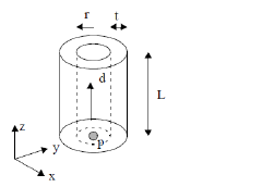
• Axis point: p
• Axis direction: d
• Inner radius: r
• Length: L
• Thickness: t