|
|
|
| 首页 >> CST教程 >> CST2013在线帮助系统 |
Helix Antenna with ReflectorTransient Analysis Examples - Field SourcesIntegral Equation Solver Examples
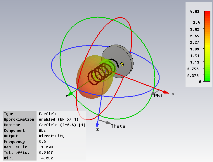
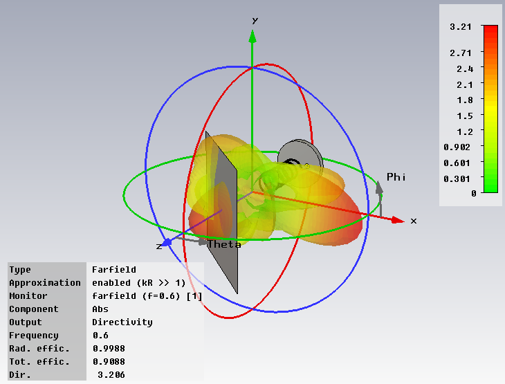
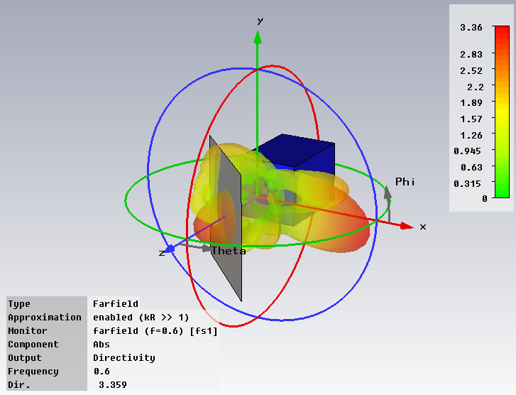
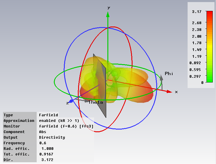
General DescriptionThis example shows the use of near and far field sources for a helix antenna and a PEC sheet scatterer. The different simulation tasks are collected in a single CST DESIGN STUDIO model in order to obtain a good overview and to be able to easily change modelling parameters and properties. Using the field sources and System Assembly and Modeling, different solver technologies can be conveniently combined in a single setup. Model SetupIn a CST DESIGN STUDIO project, the basic models of the helix antenna and the perfect electrically conducting (PEC) sheet scatterer are imported as separate CST MICROWAVE STUDIO blocks. In the layout view, these are aligned employing a parameter ”dist” for the distance of the antenna and the scatterer. Several simulation tasks are set up: The simulation task ”helix source” only includes the helix antenna as a 3D model and creates equivalent near and far field sources for the helix antenna. The time domain solver is used for simulation. Note that also the frequency domain solver could be used for this task, if more appropriate. The simulation task ”near field source and reflector” only includes the PEC sheet scatterer as 3D model and uses the equivalent near field source from the task ”helix source” as excitation. The time domain solver is used for simulation. The simulation task ”far field source and reflector” also only includes the PEC sheet scatterer as 3D model but uses the equivalent far field source from the task ”helix source” as excitation. The integral equation solver is used for simulation. The reference, the simulation task ”helix source and reflector” is set up including the full 3D model of the helix antenna and the PEC sheet scatterer. The time domain solver is used for simulation. For comparison the postprocessing task ”compare” is set up to collect results. ResultsBelow, you see the far field directivity patterns of the different simulation tasks at 0.6GHz. The ”helix source” shows the pattern of the helix antenna in free space. The other three simulation tasks show the pattern for the antenna including the scatterer. As expected, their patterns agree reasonably well.
HFSS视频教程 ADS视频教程 CST视频教程 Ansoft Designer 中文教程 |
|
Copyright © 2006 - 2013 微波EDA网, All Rights Reserved 业务联系:mweda@163.com |
|